Continue to Site

Welcome to our site!

Electro Tech is an online community (with over 170,000 members) who enjoy talking about and building electronic circuits, projects and gadgets. To participate you need to register. Registration is free. Click here to register now.

  • Welcome to our site! Electro Tech is an online community (with over 170,000 members) who enjoy talking about and building electronic circuits, projects and gadgets. To participate you need to register. Registration is free. Click here to register now.

PC monitor power-button circuitboard damaged

Status
Not open for further replies.

trandhal

New Member
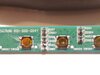
I managed to spill water on my screen yesterday, and today it doesn't turn on. I did a bit of thinking and figured that the only thing that could've possibly been damaged was the circuit board for the powerbutton and the other setting-related buttons, on the very bottom of the screen. I succesfully debezeled the monitor and found alot of corrosion on what I think are Resistors and Zener diodes (judging by the letters on the board). I know very little about electronics so I have no idea if these components are completely destroyed or not.

Is there any hope of cleaning it up (and if yes how do I best clean it?), or should I start a deepdive into finding some replacement part?
 

Attachments

  • 20210210_200006.jpg
    20210210_200006.jpg
    1.6 MB · Views: 312
If you are able to remove the PCB the best cleaning will be ultrasonic, next would use IPA (isopropyl alcohol) with a medium toothbrush. The objective is to remove the conductive salts or minerals that are shorting the different components causing a confusion in the processor. Corrosion within the small switches is the most difficult part.
 
If it turns out that the board is dead, would it somehow be possible to create a makeshift solution? Literally all I need is to turn on the screen, I never use any of the other buttons and settings. Would it be theoretically possible to create my simple own on/off switch, bypassing the dead board? I've had no luck finding a replacement
 
Not likely. Customer access controls usually operate on a voltage divider system where each function request signals the main processor chip with a predetermined voltage telling the processor to activate that request. Don't give up on cleaning. Lookup resistance ladder controls on google.
watch this.
 
Thanks alot for the help, I will keep cleaning and possibly solder up some of the joints if they seem busted.

One more question: If I plugg in the monitor and then test things with the button board, is there a risk there will be high voltage in it? Or is the buttonboard seperated from the "dangerous stuff" and it should be relatively safe? I'm thinking powering up the monitor and try different buttons to see what works and what doesn't, and I really don't feel like assembling the entire chassi between tries because it was borderline impossible to dissassemble in the first place

There's little 'dangerous' stuff in an LCD monitor - and none of it on the front buttons.

Stiff brush, alcohol, GOOD clean.

There's very few buttons anyway - so it would be trivial to create new ones for the ones you need - you just need to sort out the resistor values.
 
There's little 'dangerous' stuff in an LCD monitor - and none of it on the front buttons.

Stiff brush, alcohol, GOOD clean.

There's very few buttons anyway - so it would be trivial to create new ones for the ones you need - you just need to sort out the resistor values.
or zener diodes - ZD?
 
I am not a manufacter... I can only guess why there are zener diodes.
 
If you're going to guess, then make it an educated guess - not just something completely random.
Sorry but it was not random. Since there is no schematic you can only guess. There was not manufacter mentioned, it could be some china no brand monitor with odd quality. ;-).
Have a nice day!
 
Well, I'm back and I've had no luck whatsoever with the cleaning. Board is still dead and I've found no replacement parts online (unless there is some secret website that has it that I haven't found).

As a last resort, how likely would it be that a similar powerbutton board for a similar monitor model would work? Assuming that it's the same connector and I can physically plug it in to the motherboard, is it likely that it could turn on the monitor? Literally all I need it to turn on the display, I don't care about any of the other settings.

If it's exactly the same monitor (even if the name on the front is different) then it should work, but if it's at all different then it won't - there's no standard system or connection for front panels.
 
Well, I'm back and I've had no luck whatsoever with the cleaning. Board is still dead and I've found no replacement parts online (unless there is some secret website that has it that I haven't found).

As a last resort, how likely would it be that a similar powerbutton board for a similar monitor model would work? Assuming that it's the same connector and I can physically plug it in to the motherboard, is it likely that it could turn on the monitor? Literally all I need it to turn on the display, I don't care about any of the other settings.
I think it will be better to modify it or create a new one. Measure voltage on connector to logic board, take 10k res and place it on vcc and other pins. If mcu switch at 0V logic (connect res between gnd and other pins) than you will need probably lower resistor value (470R would be safe for 12v if you connect mistakely 12v to gnd) . Becouse it will act as resistor divider.
But before i will try continuity chec on board
 
If it's exactly the same monitor (even if the name on the front is different) then it should work, but if it's at all different then it won't - there's no standard system or connection for front panels.

I managed to find this:
(I hope links work).
I have a VP278QG, and the items listed is for a VP278. I can see some differences on the motherboard (mine doesn't have VGA for example). But the important part, the powerbutton board, looks identical.

It should, on a theoretical level (and assuming it's functional), work for mine, right?
 
I f you have no other options then you might try removing the unused Switches to rule out those being shorted internally. A cheap multi-meter and soldering iron would help . Also the board numbers shown in link and your original photo appear the same
 
I think it will be better to modify it or create a new one. Measure voltage on connector to logic board, take 10k res and place it on vcc and other pins. If mcu switch at 0V logic (connect res between gnd and other pins) than you will need probably lower resistor value (470R would be safe for 12v if you connect mistakely 12v to gnd) . Becouse it will act as resistor divider.
But before i will try continuity chec on board

Have I missed something in this thread? - or have you randomly invented 12V again?
 
Status
Not open for further replies.

Latest threads

New Articles From Microcontroller Tips

Back
Top