D.Doerschuk
New Member
Hello Everyone,
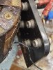
This is my first post, and I'm afraid my question is pathetic. Here goes: I'm rebuilding the carriage drive to an old lathe, and the manual controller uses a Superior Electric Powerstat Type 21 (specifically, 21-1004). The field wiring comes into 5 screw terminals and attaches normally to the front of the bakelite terminal board. The factory connections to the coil and wiper are made to ~~24 AWG solid wire connectors at the rear of the 5 screw terminals. The embarrassing part of my question is that while cleaning up the Powerstat I broke off one of the factory wires at the connector. The pathetic part of my question is that I cannot see how to re-open the rear-of-terminal connector to install a spankin' new wire. I have pushed, turned, pulled, removed the front terminal screw and looked inside, and danced the Dance of Humiliation. Shown below is a photograph of the back of the bakelite terminal board.
I did say this was pathetic.
Please help.
Thank you!
Dave