Continue to Site

Welcome to our site!

Electro Tech is an online community (with over 170,000 members) who enjoy talking about and building electronic circuits, projects and gadgets. To participate you need to register. Registration is free. Click here to register now.

  • Welcome to our site! Electro Tech is an online community (with over 170,000 members) who enjoy talking about and building electronic circuits, projects and gadgets. To participate you need to register. Registration is free. Click here to register now.

Parking Car ElectroMagnetic Sensor

Status
Not open for further replies.
Yes I know. In fact if I put dual voltage (+Vdd and -Vdd) the circuit oscillates.
I would buld one with single supply.
Regards
 
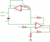
I prefer to use the opamp because I would have stable oscillations.
I found some single supply voltage opamps, like LM386 and LT1006.
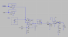
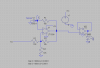
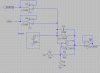
Find the attached circuit.
Now, the problem is this.
If the object is near the sensor, the capacitance will increase, maybe to some % of farad, and the frequency of the oscillator will decrease toward a a dc value. If the object i far, in theory the capacitance should be 0. As the object disappear the frequency will increase.
At the limit, it should be infinity, but I think that a dc value will appear.
So, in order to detect the object, I thnik to add a counter of pulses.
Is it good?
 

Attachments

  • relaxation.png
    relaxation.png
    9.4 KB · Views: 343
giusepped said:
So, in order to detect the object, I thnik to add a counter of pulses.
Is it good?

You can do it with a frequency counter. You still need to get from the frequency counter to a logic signal.

What I did was use the tone decoder chip which set a "no object" frequency. Then as an object appeared, the tone shifted and the output state of the chip changed. That was my logic signal. I believe the LM567 chip is listed as obsolete, but it is still in good in the US. There may be substitute chips available or use a microcontroller. John
 
Somep roblem

I did this circuit(in simulation).
But I really do not understand why the output is not 0-9v and instead it is 1.8-7.5 range.
I forgot something?
Any reply appreciated
G
 

Attachments

  • relaxation2.png
    relaxation2.png
    10.1 KB · Views: 352
  • plot.png
    plot.png
    2.5 KB · Views: 279
I guess the real queston is why you need it to go rail to rail. What's wrong with what you have, at least as a start. You could then focus on the rest of the circuit and come back to the oscillator, if you like the results from the capaciflector. I would also sugggest reconsidering the logic-based oscillator at 12V, single supply. John
 
Final

I will build the following circuit, which seems to work (in simulation)
Goodluck (to me)
 

Attachments

  • final.png
    final.png
    12.7 KB · Views: 325
jpanhalt said:
I guess the real queston is why you need it to go rail to rail. What's wrong with what you have, at least as a start. You could then focus on the rest of the circuit and come back to the oscillator, if you like the results from the capaciflector. I would also sugggest reconsidering the logic-based oscillator at 12V, single supply. John

Because I would build also a PIC which accepts the oscillator output, but this circuit for a second step. PIC accepts TTL logic values, 0/5V.
 
Ok, I'll do it.
The truth is that my local store does not have all the components too!

Anyway, I'am near the prototype. One more thing.
The frequency of the oscillator increases as the object disappear, and decreases as the object is approaching. since I would test the circuit by my ear (see the LM386 in the previous circuit) I was wondering if there is a technique to "convert" the frequency.

I was thinking to a VCO...
 
giusepped said:
Ok, I'll do it.
Anyway, I'am near the prototype. One more thing.
The frequency of the oscillator increases as the object disappear, and decreases as the object is approaching. since I would test the circuit by my ear (see the LM386 in the previous circuit) I was wondering if there is a technique to "convert" the frequency.

I was thinking to a VCO...

I am not sure how a voltage controlled oscillator (VCO) would help you. What you describe is a frequency to voltage converter. Search on "tachometer". For example, see: https://pdf1.alldatasheet.com/datasheet-pdf/view/103466/NSC/LM2917N-8.html

A simple oscilloscope or a multimeter with frquency display will help you. Although, for proof of concept, the your ear is pretty good at discriminating tones. John

Edit: A simple low-pass filter with passive components may work. See: Horowitz and Hill, 2nd edition, page 618. There are other circuits based on op-amps (ibid, Chapter 9, regarding digital to analog conversion).
 
Last edited:
NOt yet

I mounted the circuit I posted.
UNfortunately, I cannot hear anything from the speaker (4ohm)
I still do not own an oscilloscope so I cannot say if the oscillator oscillates.
Anyway, I put a led at the output of the voltage follower and it runs.
The multimeter says about 2.2 v there.
I think LM386 does not like square waves...
Anyway, I ordered a used oscilloscope and in a day I should be able to test more accurately.
In the meantime, there is another way?
G
 
giusepped said:
I mounted the circuit I posted.
UNfortunately, I cannot hear anything from the speaker (4ohm)

I don't understand how that statement agrees with your earlier statement:

giusepped said:
The frequency of the oscillator increases as the object disappear, and decreases as the object is approaching. since I would test the circuit by my ear (see the LM386 in the previous circuit)...

In any event, you will find it much, much easier to troubleshoot with the oscilloscope. Which oscilloscope are you getting? John
 
What dont you understand?
Did you remember my previous circuit?
I attached the LM386 in order to drive the speaker. Its input will be a square wave, from the oscillator.

Anyway, the oscilloscope is a 100 mhz tektronix (used from yahoo auction)
G
 
Got working

I made the following circuit and it seems to oscillate.
But I don't understand why.
Moreover, the capaciflector must be circular. I used two shapes, one was a rectangular shape and the second one is circular.
With the rectangular shape, nothing happens at the oscilloscope.
With the circular shape, I can appreciate some 1KHz variations in the rectangular waveform.
Somebody can explain to me why the circuit oscillate?
I know that this is relaxation oscillator, but the capacitance of the sensor is very high and in theory it should not oscillate. I am missing something?
 

Attachments

  • temp.PNG
    temp.PNG
    8.5 KB · Views: 269
Status
Not open for further replies.

Latest threads

Back
Top