Gabrielle
New Member
Hi All, firstly let me appologize for my total dumbness and thank you for helping me in anyway you can.
What im doing is trying to build a simple parallel output device, that can be use to control different household items. Now, I've spent lots of time online surfing, and found http://www.hut.fi/Misc/Electronics/circuits/parallel_output.html after reading and researching alot of posts on your site. Now my problem is this, due to the fact that its been like 20+ years since i took Control Technology at school, I don't know what some of the symbols are on the circuit diagram (Im sorry.. but im trying to understand it and get back into to electronics so during the day when alone i have something to tinker with - who said mum's just read and watch tv hehe)
What im asking I guess is this, the diagram that im reading and re-reading is confusing me on the components needed, and also once I know whats what, then need to find some good software, to design the board, and test it, so i can show it to a sales person at maplin so not to look a total dumb blond. :lol:
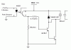
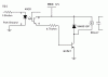
The diagram is the last one the Optosiolated higher Power Circuit on the site, and its the last diagram thats presented before the code at the end.
Any and ALL help is greatly appreciated.
Yours
Gabrielle
What im doing is trying to build a simple parallel output device, that can be use to control different household items. Now, I've spent lots of time online surfing, and found http://www.hut.fi/Misc/Electronics/circuits/parallel_output.html after reading and researching alot of posts on your site. Now my problem is this, due to the fact that its been like 20+ years since i took Control Technology at school, I don't know what some of the symbols are on the circuit diagram
(Im sorry.. but im trying to understand it and get back into to electronics so during the day when alone i have something to tinker with - who said mum's just read and watch tv hehe)What im asking I guess is this, the diagram that im reading and re-reading is confusing me on the components needed, and also once I know whats what, then need to find some good software, to design the board, and test it, so i can show it to a sales person at maplin so not to look a total dumb blond. :lol:
The diagram is the last one the Optosiolated higher Power Circuit on the site, and its the last diagram thats presented before the code at the end.
Any and ALL help is greatly appreciated.
Yours
Gabrielle
") thanks once more. guess ill have to make that one and see if it works once more.. :lol:
thanks once more. guess ill have to make that one and see if it works once more.. :lol: