Continue to Site

Welcome to our site!

Electro Tech is an online community (with over 170,000 members) who enjoy talking about and building electronic circuits, projects and gadgets. To participate you need to register. Registration is free. Click here to register now.

  • Welcome to our site! Electro Tech is an online community (with over 170,000 members) who enjoy talking about and building electronic circuits, projects and gadgets. To participate you need to register. Registration is free. Click here to register now.

Panasonic RF4800 SW. Ooops! Help!

Status
Not open for further replies.

cdnpont

New Member
Hello Electro Tech,
First post,

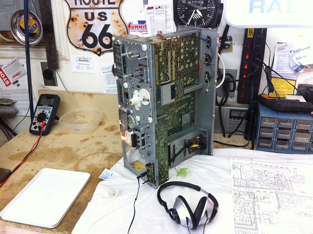
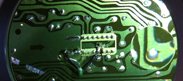
Just recently acquired a 1980 vintage Panasonic RF4800 analog SW radio. Opened it up, replaced a burned out lamp with an Led, and all was well with the unit working very well...until today. I'd decided since the unit was dual power (AC/12v int/ext bat), that I would try it on battery power to see if I could reduce the RF noise from the power supply transformer, which had previously been changed to a large wall adapter mounted inside on the place where the old transformer mounted.. Guess what? I got the bat DC polarity backwards, and upon turning the radio on I instantly heard a little pop through the speaker and realized what had happened. Returning to AC power, now I have no audio. Lamps and the digital display still light. Slight burnt smell present. Opening it up I seen no sign of burning on the Power or AF amp board. The power in board has no visible fuse. I have voltage right out to the power amp board plug, and out into the board, but I don't have near enough electronic knowledge to know where to trace further.

Question;
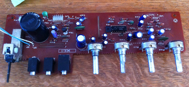
What would have gave way on the power amp board ? Is there a built in component that would fail on reverse polarity to protect the rest of the board/radio? f I can figure that out, I have the capability to remove the board, remove and replace the component. Failing that, It goes to someone qualified to repair it...but I'd like to learn. I just hope I haven't really screwed this sweet vintage radio up.

Any help or thoughts greatly appreciated,

Cheers, and thanks,
Mark

33648858576_2b3d9eaca7_z.jpg


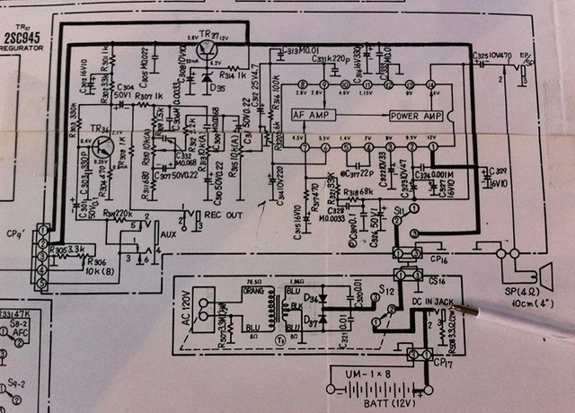
Pen shows the DC in point.
 
The audio amplifier IC is probably burned out. I doubt that you will find a replacement today. Kiss the radio goodbye and bury it.
Wait a minute. Make or buy an audio amplifier for it.
 
Thanks for the reply,

Yea, I feared I might have dinged the IC. You figure they might have put a diode in to protect the unit is this event... 37 years old and then I show up. Go figure.

I poked around and checked some of the capacitors and they all came up. The body of the chip looks fine, no burning or melting and there is voltages at the pins, but that probably means little.

Perhaps I could find a parts radio. All a shame since the thing is cosmetically 10/10.
Maybe I'll move on to something better. Live and learn I guess. At least I don't have a ton into it.

Cheers, Mark
 
An "idiot" diode will reduce the maximum output power. Some car radios have a huge diode parallel (not in series) with the radio so if the voltage is connected with backwards polarity then the diode protects the radio and blows the fuse.
 
If you have a pair of amplified pc speakers connect them temporarily to the radio as the audio amp/speaker, the volume control if its a mechanical pot is a good place, if its a digital volume control google some of the ic's in the audio section and see if you can find where the audio signal is.
An Lm386 is a quick to build audio amp, not hifi but enough for Sw listening, and you ought to be able to make one on a small piece of veroboard and tuck it out the way somewhere, if you google Lm386 you should find lots of circuits.
You might need to unsolder the old audio amp chip if its drawing parasitic current.
 
The LM386 is hifi because below clipping its distortion is only 0.2% that not many people can hear and its frequency response goes absolutely flat to 100kHz. You might hear a little hiss when the voices stop.
 
Thanks for all the reply's! They've inspired me to dig a little deeper.

I can get a single IC chip to replace the damaged one. Obsolete, but is still available. I believe it's a NEC UPC 1018C. So taking advice from Dr Pepper, I stated probing around to see if I at least have an unamplified output...I do! In the Rec out (seen as Rec Out on the schematic) with headphones on. Fixed output of course, no volume, bass or treble... but all the bands are at least active, which is good as the turner might have survived relatively unscathed. All the lights, and the VU meter work.

Do I attempt to restore the amp board? I'm at the point I can easily remove it. With a little help I just might be able to pull this off. Doesn't seem like too much trouble to cut the IC out, unsolder and clear the pins. Solder in a IC socket then figure out what else has been compromised. Test/replace.

For starters, how can I test a Transistor on the board?

Cheers, Mark

33551211202_a276e8f1eb_z.jpg
 
Last edited:
Well, it's not a NEC IC. Believe what you will from the web at your own peril...
It's a 14 pin labelled as LA4201 8G5.

Yet to track it down. If I can't, could I just replace it with a diy circuit board?

33551799662_b0d96c0bfe_z.jpg


La4201,
32894312363_fe94523844_z.jpg
 
After all considered, and with the excellent suggestions here, I'm going to put together a little LM386 amp that can hopefully use my existing volume, bass and treble pots as they sit, the 4th pot, the BFO pitch will stay as is as sits, as it's functioning normally. I'll also make use of the the aux and rec out jack fed from the new mini amp. I hope the signal I'm getting off the rec out will be good enough to amplify. I does sound fairly clean.

I had no idea about that excellent little LM386 chip, and am excited to get it on a breadboard for a mock up. It's been a long time since I did an electronics project.

Anyway, any suggestion as to which pins on the IC I should terminate ? 1, 6 and 9? Might as well isolate it.

Thanks again for bearing with me,
Mark
 
Glad to be of assistance.
Looking at the schem the tone controls are seperate to the amp itself, audio going to pin 9 of the ic so personally I'd keep the board and make a little board up with an amp ic on it and hot glue it to the audio board. I notice there is what looks like some Eq on the existing amp, a new amp might sound a bit different.
If you can get the original ic it would make things a lot easier, might be worth looking into whether the upc101 is the same as the La4201, it wouldnt surprise me if they are interchangeable, the manufacts may have swapped out the chip from the schem as they got a load cheep.
Someone of your capability and interest ought to have a transistor tester, you can get them really cheap from ebay. You can test a tranny with a multimeter to an extent, theres loads of stuff on youtube about this, personally I use an octupus component tester, this does require a 'scope and a little practice.
Heres a super simple circuit for the Lm386, you can omit the cap between pin 1 and 8 to reduce the gain if the volume pot is too sudden, lower values like 4u7 2u2 etc give reducing amounts of gain. Looks like on your old amp chip pin1 is +supply and pin 12 is gnd, so long as you pull the original ic you could connect the o/p of the Lm386 amp to pin 14 and use the original speaker and 'phone jack, in fact all the wires to the Lm386 can go back to the original audio amp ic connections.
https://www.eleccircuit.com/lm386-audio-amplifier-circuit/
 
Last edited:
The datasheet for the LM386 shows that it works well (0.45W before clipping distortion) with a 9V supply and an 8 ohm speaker. With a supply voltage above 9V the output power is not increased but the heating is increased instead. With a 4 ohm speaker the output power is less than with an 8 ohm speaker and with a 4 ohm speaker and a 12V supply then the IC is close to overheating, but not producing much power (0.3W before clipping distortion) in the speaker.
 
Thanks again for all the suggestions,

I have a LM386N-1, but it looks like the original LA4201 is actually still available. All things considered, to start, do you think I should at least try to replace the chip?
On my own, I could certainly clip out the chip, then desolder and remove the pins. But could I successfully solder in the replacement? It might be challenging to keep the heat out of the chip, and the solder points are quite fine. I can solder, just not sure about something this fine.
Should this be left to a Tech to replace? Perhaps I should just take the board to someone for chip replacement, and further testing for other damage?

Cheers, Mark

33351620930_52bde702ca.jpg
33736665625_ee1804e8b6_z.jpg
 
On my own, I could certainly clip out the chip, then desolder and remove the pins. But could I successfully solder in the replacement? It might be challenging to keep the heat out of the chip, and the solder points are quite fine. I can solder, just not sure about something this fine.

That's not a fine pinned chip, just a standard 0.1" one - dead simple to change.

The only 'slight' concern is the heatsink tabs, but that's only while removing the old one, it's quick and easy to solder in the new one.

All I'd do is unsolder the 14 pins with a solder sucker, then heat the heatsink tabs (going from one to the other, preferably with a decent size bit) while levering it up gently with a screwdriver. This would actually remove the chip in perfectly useable condition.
 
Thank you for the suggestion. I simply clipped the pins off the IC and the chip pulled up, breaking free of the heat sink. I'll heat the sink to pull it free of the board. I believe to IC is toast, so it's no loss that it's destroyed.
I've bought 2 of the NOS chips.
Must I heat sink each pin at the chip when soldering? Or if using low heat, will the chip handle it?
 
Unless you are excessively cumbersome while soldering there's no need to heatsink at all, I never have over many decades - each pin should only take a second or two to solder - although the heatsink tabs will take considerably longer.
 
A hand-operated solder sucker is inexpensive and works well for removing parts. The good ones have a spring pushed piston in a cylinder (slurp!). The cheap rubber bulb ones are no good.
ICs are designed to be soldered using a soldering iron at the correct temperature (cheap soldering irons get too hot and are not tinned properly), using 63/37 rosin core solder. Each pin is soldered in about 1 second with 1 or 2 seconds of cooling in between soldering each pin. I hope your replacement old ICs are not fake ones from ebay.
 
If you get it working and want to prevent future reverse polarity damage you could add a MOSFET as an ideal diode in series with the DC input to block any reverse voltage, as shown here.
 
A hand-operated solder sucker is inexpensive and works well for removing parts. The good ones have a spring pushed piston in a cylinder (slurp!). The cheap rubber bulb ones are no good.
ICs are designed to be soldered using a soldering iron at the correct temperature (cheap soldering irons get too hot and are not tinned properly), using 63/37 rosin core solder. Each pin is soldered in about 1 second with 1 or 2 seconds of cooling in between soldering each pin. I hope your replacement old ICs are not fake ones from ebay.

Great tips on chip soldering,

Looked at the suckers as you suggested, not sure about them, many choices. Will a desoldering wick be of any use? I bought a 3mm width ribbon of it. I hope the chip is legit.
I'm new to the chip thing...can't see why such an old obsolete chip would even be advertised (the radio was manufactured in 79). USA Seller is 99.9% positive with 3600 sales if that means anything.

I'm going out to see if I can at least mock up the LM386 to the board in such a way that I get some amplification.

We can hope! Cheers.
 
I've soldered lots of ic's and never blown one, dont worry about it.
In fact I've salvaged ic's from boards by heating them in an old toaster oven, they've been hot enough to melt solder for minutes and still worked afterwards.
Snipping each pin off first then removing then one by one is a good idea, put a marker dot on pin one end so you dont forget.
The radio will work as before with its correct chip, the '386 isnt as powerful so may not sound quite as good.
There are lots of sellers supplying obsolete ic's, it obviously makes money.
 
Status
Not open for further replies.

Latest threads

New Articles From Microcontroller Tips

Back
Top