Willen
Well-Known Member
Hi,
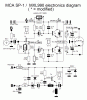
It's said that in a balanced audio circuit, both side of components should be paird/matched to supress noise perfectly. I am getting many circuit of MXL Condenser Microphone around internet. Here is circuit attached which has been improved in right side, and original is in left; taken from here: https://www.pa0nhc.nl/AudioTechniek/mxl990_sp1mods/mods_en.htm
Look at the R6 and R7, these are phase splitter FET bias resistor around drain and source. All people recommend to use paired 2k2 in both side which means these resistors will have equal (pretty close) resistance. BUT, look at the R13 and R14 which are in series and are connected as parallel with R6 (one of the matched pair of 2k2). Because of the parallel additional resistor in the source, the value of paird 2k2 will decrease overall. Look at the modified circuit, modifier added even lower value resistor which will decrease the value of paired resistor (ok, total resistance in source) even more. So, What is the worth of pairing these resistors in this case? Or what you suggest? Please!
Attachments
Last edited:
")
