Continue to Site

Welcome to our site!

Electro Tech is an online community (with over 170,000 members) who enjoy talking about and building electronic circuits, projects and gadgets. To participate you need to register. Registration is free. Click here to register now.

  • Welcome to our site! Electro Tech is an online community (with over 170,000 members) who enjoy talking about and building electronic circuits, projects and gadgets. To participate you need to register. Registration is free. Click here to register now.

Overcurrent Shutdown For power supply

Status
Not open for further replies.

Alexsgarage

New Member
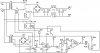
I have built a power supply for an induction heater. It's output is 112V DC and I want to add a small transformer to the output of the main transformer to measure current and to shut the circuit down if the current becomes larger than the transformer is rated for. The power supply can be shut down by turning off power to the main relay. Is there a circuit that can accomplish this?:confused:
 
to shut the circuit down if the current becomes larger than the transformer is rated for.

A transformer can tolerate a very large overload before thermal stress sets in.

A quick-acting overload sensor will invite nuisance tripping.

Simplest solution is a thermal sensor switch, attached to the transformer.
 
Ya good point, I will add some sort of delay to the overload sensor and if the current goes back to the normal rated current of the transformer within the specified time then the sensor will not shut down the supply.
 
I have designed a ciorcuit using an LM393 comparator, the reference voltage is set with a potentiometer and a reverse biased zener diode, and the input is from a small transformer on one of the outputs of the main power transformer. Also, I used a capacitor to control the timing of the detector to only trigger it if the overload lasted over a predetirmined period of time. :)
 
The two LM393 comparators do not have a pull-up resistor, so I dont think your circuit will work because there is nothing that will pull the gates of your funky p-chan/n-chan inverters high.

Why even use the funky inverters? Just reverse the inputs on the comparators, and their outputs will swing the right way. Just add a 4.7k to 47K pull-up resistor between the 393 outputs and the positive rail.
 
There's a few things that won't work, that need sorting out first.

Would you like me to list all the points that's wrong?, or are you already aware of them?

Plus if you don't mind me saying, it's a bit long-winded how it goes about what it does :) If you're building it yourself, you'll probably prefer it to be least number of parts as possible.
 
Last edited:
Ok, so the schematic is fixed.:)
 

Attachments

  • Untitled.jpg
    Untitled.jpg
    95.5 KB · Views: 246
Last edited:
What exactly is T4? If the T4 is a closely-coupled transformer, you've got what amounts to U21 in carrying the current of the protected supply. Is it a current transformer? If so, where'e the Burden resistor? I've not analysed much further than that, apart from noticing there's a lot of parts to do a little job :)
 
Last edited:
The burden resistor is 25 ohms. T4 is a toridial transformer around the output of the power transformer.
 
Last edited:
OK, the 25 ohm wasn't shown, it threw me.

If it's only the transformer that's being protected, why not a thermal sensor attached to the outside of the windings like they have on arc-welders?

If you want a delayed overcurrent trip, you could reduce the parts count to 1/10th of what you have now, by replacing T4 with a resistor and have a thermal switch clipped to it.
8371-Thermal_sensor.summ.jpg
**broken link removed**
 
Last edited:
Status
Not open for further replies.

Latest threads

New Articles From Microcontroller Tips

Back
Top