Continue to Site

Welcome to our site!

Electro Tech is an online community (with over 170,000 members) who enjoy talking about and building electronic circuits, projects and gadgets. To participate you need to register. Registration is free. Click here to register now.

  • Welcome to our site! Electro Tech is an online community (with over 170,000 members) who enjoy talking about and building electronic circuits, projects and gadgets. To participate you need to register. Registration is free. Click here to register now.

Oshonsoft PIC Simulator

Status
Not open for further replies.
hi TT,
If you mean a stepper motor, there is one already one in Oshonsoft.?
 

Attachments

  • AAesp01.gif
    AAesp01.gif
    19.3 KB · Views: 443
  • CapDis1.bas
    1.1 KB · Views: 396
  • CapDischarge1.exe
    52.5 KB · Views: 379
Last edited:
Thank you eric, i ran 2 instances connected to porta.0,b.0 and it does just the job,using the portb.0 one also to sim interrupt on pin change etc.
many thanks i owe you some beers if you are ever up this neck of the woods.
many thanks again all the best
 
Hi
Shall you give me programming for follwoing sequence?
After the circuit is switched on:
1. Able to set two countdown timers t1 and t2
a. Display t1 at the start up (t on the left 7-segment display(7SD) and 1 on the right 7-segment display(7SD) (here after referred to as 7SDL and 7SDLR respectively))
b. Then press enter push to on switch(here after referred to as PSE) connected to RA0 which allows us to change the time
c. Time is changed using increment and decrement push to on switches (here after PSI and PSD respectively))
d. Press PSE to set t1
e. t2 is displayed on the 7SDs(t on 7SDL and 2 on 7SDR)
f. Time is changed using increment and decrement push to on switches (here after PSI and PSD respectively))
g. Press PSE to set t2
2. Now Stepper Motor(SM here after) which is connected to port B ( B1,B2 to one coil (black and blue wires of the SM (green and red wires of SM in that order)) and B3, B4 to another coil (green and red wires of SM in that order)) starts rotating in one direction, say clock wise (CW) (which is same on each start-up of the circuit).
3. During rotation, a knob which is connected to the shaft of the SM now comes in proximity of the first proximity sensor (PS1) and corresponding output (OP1) is generated. This output is given at RA3. Now the SM halts at this position for t1 i.e., no output on B1-B4.
4. After t1 SM starts rotating in reverse direction i.e., anti clock wise (ACW)
5. During rotation knob comes in the proximity of the second proximity sensor (PS2) and corresponding output (OP2) is generated. This output is given at RA4. Now the SM halts at this position for t1 i.e., no output on B1-B4.
6. After t2 SM starts rotating CW again
7. Steps 3 through 6 repeat till the circuit is on.
Please help me with the programming. The micro controller I am using is PIC16F72.
Hi,
I have written, using Visual Basic 5, a number of External Modules for the simulator.

Some are available on the Oshonsoft site.
They include:
Push buttons, latching and momentary.
Analog ADC inputs
Keypad 4*4
Edge Switch 4 bank
Stop Watch, measures program loop times
TPIC6595a
25C0409 SPI

If anyone is interested in getting a copy of these programs or if they have a particular piece of hardware they would like to simulate, let me know.
I will let you know if I can do it!:rolleyes:

Also I would like to hear from members who have written modules and are willing like to share.
 
hi,
The program that you are asking for, is not a simple task.

You should post the sections of the program that you have written, so that we can help with the problems you are having.
 
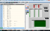
To start with I am writing a program which increases or decreases the number displayed on multiplexed 7segement displays. I am using real pic simulator for testing. The connections shall be seen from the attached screenshot of the real pic simulator. on the 7 segment displays only 8 or 6 is seen on successive pushes on push button connected to porta1 and port a2. Please tell me where i am going wrong. Following is the c code

int j;
unsigned char seg[10]={0x80,0xf2,0x48,0x60,0x32,0x24,0x04,0xF0,0x00,0x30}; //unsigned char *ptr[10][8],seg[10][8]={{1,0,0,0,0,0,0,0,0},{1,1,1,0,0,1,0,0},{1,0,0,1,0,0,0,0},{1,1,0,0,0,0,0,0},{0,1,1,0,0,1,0,0},{0,1,0,0,1,0,0,0},{0,0,0,0,1,0,00},{,1,1,1,0,0,0,0,0},{0,0,0,0,0,0,0,0},{0,1,1,0,0,0,0}};//array for pushing numbers into 7segment display from 0 to 1
void display(int);
void main()
{
int i=0,k=0;
TRISA = 0xE7 ; // set PORTA pins 3,4 as output and others as INPUT
TRISC = 0x01 ; // set PORTB as OUTPUT except pin0
TRISB = 0xE1 ; // set PORTB pins 1,2,3,4 as OUTPUT others input
while(1) // forever
{
display(i);
if( PORTA.f2 == 1)
{
if (i<99) i++;
else i=0;
display(i);
}
else if (PORTA.f1 == 1)
{
if (i>0) i--;
else i=99;
display(i);
}
k++;
}
}
void display(int l)
{
PORTA.f4 = 0;
PORTA.f3 = 1;
j=l%10;
PORTC = j;
delay_ms(1);
PORTA.f3 = 0;
PORTA.f4 = 1;
j=l/10;
PORTC = j;
return;
}
 

Attachments

  • seven segment display on real pic simulator.png
    seven segment display on real pic simulator.png
    171.5 KB · Views: 404
  • steppercontroller.asm
    4.1 KB · Views: 356
hi,
I will try your asm file in Oshonsoft, let you know what I find by tomorrow.

EDIT:
Checked your asm program, its only a fragment of the whole program.!
I cannot debug that, sorry.
 
Last edited:
shall you give a small program on how to do polling with portA pins as inputs.

hi,
I will post a simple program in Oshonsoft Basic showing PORTA polling for a 16F72 PIC.

EDIT:
Attached a PORTA poll for 2,1,0 pins, IF High PORTB 2,1,0 will go High

Basic and Asm file attached.
 

Attachments

  • PollA.asm
    1.4 KB · Views: 348
  • PollA.bas
    325 bytes · Views: 379
Last edited:
Eric, sorry to jump in on this thread but this is my first post, and I needed to contact you....
I'm evaluating OshonSoft's PIC SImulator IDE, and it's good, going to purchase if I can get one thing to work for me... I've written an external module in VB6 based on the template provided, but when I try to add it via the tools menu, I get an error indicating the PICSim app can't establish a connection with my compiled app. I can set regs etc IN the sim app, but I'm guessing it won't get updates from the app. You've successfully created these modules, so I wondered if I could I for your assistance? Zip of VB project attached (I hope)
Regards, Nick
 

Attachments

  • StatusFlags.zip
    10.9 KB · Views: 210
hi Nick,
Its a 6 year thread.:woot:
Have downloaded your zip, will look it over, if I can help I will repost.

A problem is that Vlad of Oshonsoft has modified his PIC IDE files over time, so some features no longer work.
Let you know what I find.

Eric
 
Hi Eric, yes, an old thread indeed. Unfortunately my unfamiliarity with the message board didn't permit my contacting you directly, my humble apologies. Regarding my VB, I worked it out... my VB app was OK, I just wasn't entering the correct details in the simulator external modules field doh! I've been totally side tracked from the project I was pursuing by revisiting my dabblings with PIC microcontrollers, and still having a bunch of 16C84's to hand, I got to playing with MPLAB and stumbled upon Oshonsoft's PIC simulator..... well, I'm having great fun with this very old chip, and it's revived my passion for PIC assembly language (I know, C, C++, Basic etc, but I love it). The simulator seems great, and the ability to extend its capabilities means many further hours of distraction. Many thanks for your kind attention. I do hope I can call upon your expertise should I get into any further difficulties Eric.
Regards, Nick
 
hi Nick,
I have already modified your VB6 to run on myVB5 program.
It gets as far as displaying the Status Form image, but at the moment connect with the PIC IDE, I will try to find out why, just for the heck of it.

If you look at my ETO Blogs there are some oldie Oshonsoft Tools that may interest you.

There are some 'short comings' in Oshonsoft, but as a entry point system its OK.

Eric
https://www.electro-tech-online.com/blogs/oshonsoft-pic-ide-external-modules.5/
 
hi Nick,
Try this routine in place of your Test button routine.
Run the Oshonsoft NickTest1.bas, it just increments the STATUS register.
[ change the NickTest1.txt to .bas after downloading

On pushing the Test Button the VB will read the STATUS reg and output on the VB form and also set PORTB pins

Unrem the rpt for continuous run
BTW: I used a 16F877 for demo.

Eric


Private Sub cmdTest_Click()

Dim i, X, b As Integer


'''''''''rpt1:
b = 1
i = object1.getreg(ccSTATUS)

For X = 0 To 7

If (i And b) <> 0 Then
lblStatus(X).Caption = "1"
object1.setpinstate ccPORTB, X, 1
Else
lblStatus(X).Caption = "0"
object1.setpinstate ccPORTB, X, 0
End If

b = b * 2
Next X
DoEvents ' IMPORTANT!!!!!!

'''''''''GoTo rpt1
 

Attachments

  • NickTest1.txt
    240 bytes · Views: 214
Last edited:
Status
Not open for further replies.

Latest threads

New Articles From Microcontroller Tips

Back
Top