Musicmanager
Well-Known Member
Hi Guys
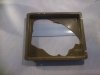
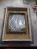
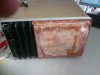
Some of you may remember, a while ago I bought a cheap CRT 'Scope to use and experiment with so that I'd learn when and where to use it properly. Based on the advice from here, the first thing I did was to strip it down and clean out the 47 tonne of dust and dirt. All went well until I removed the back panel to clean the power board and to my horror I discovered it had at some time suffered a major impact causing a large circular crack which had been repaired with superglue. It didn't seem to be rocket science to work out that the back panel in that condition was offering no protection whatsoever and the rear end of the CRT was just next to it. So I decided to try and repair it or rather to replace it.
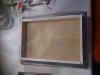
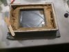
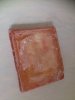
I made a casting mould from some old plasterboard, filled it with some very runny finish plaster and then pressed the old panel into it and left it to set. Then removing the old panel left a perfect negative shape of the panel which I filled with fibreglass matting and resin left over from the last time I repaired the wife's car.
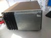
A little trimming with a sander, some screw holes, a trial fit and a light spray with some best quality Holts and I have a serviceable, if not the prettiest of replacement panels.
There are some pics below for the benefit of my gloating sense of pride !! Can I now say ' I repaired an Oscilloscope ?? '
S
Some of you may remember, a while ago I bought a cheap CRT 'Scope to use and experiment with so that I'd learn when and where to use it properly. Based on the advice from here, the first thing I did was to strip it down and clean out the 47 tonne of dust and dirt. All went well until I removed the back panel to clean the power board and to my horror I discovered it had at some time suffered a major impact causing a large circular crack which had been repaired with superglue. It didn't seem to be rocket science to work out that the back panel in that condition was offering no protection whatsoever and the rear end of the CRT was just next to it. So I decided to try and repair it or rather to replace it.
I made a casting mould from some old plasterboard, filled it with some very runny finish plaster and then pressed the old panel into it and left it to set. Then removing the old panel left a perfect negative shape of the panel which I filled with fibreglass matting and resin left over from the last time I repaired the wife's car.
A little trimming with a sander, some screw holes, a trial fit and a light spray with some best quality Holts and I have a serviceable, if not the prettiest of replacement panels.
There are some pics below for the benefit of my gloating sense of pride !! Can I now say ' I repaired an Oscilloscope ?? '
S
")
