Continue to Site

Welcome to our site!

Electro Tech is an online community (with over 170,000 members) who enjoy talking about and building electronic circuits, projects and gadgets. To participate you need to register. Registration is free. Click here to register now.

  • Welcome to our site! Electro Tech is an online community (with over 170,000 members) who enjoy talking about and building electronic circuits, projects and gadgets. To participate you need to register. Registration is free. Click here to register now.

Oscillator circuit

Status
Not open for further replies.

zachtheterrible

Active Member
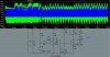
Hello all, I've got a couple simple questions about this oscillator here.

Can I put the antenna where the green arrow is pointing? Cuz it's getting a lot more voltage than the blue.

Why have the two coils? Y not just 1?

Any improvements that I could make to this circuit?

Finally, the green voltage is going down to -21 volts, is there any way of making it go down to 0 volts, and therefore get a better amplitude?

Thanx SOO much for your help :eek:
 

Attachments

  • 2_coil_fm_transmitter_cad_202.jpg
    2_coil_fm_transmitter_cad_202.jpg
    41.6 KB · Views: 559
L1 and L2 is actually one coil with a tap. The tap makes it an impedance transformer so the Q of the coil is improved, making it more stable. If you did not model it as a transformer, you will not get the expected results. The impedance of a 1/4 wave antenna is about 75 ohms, so it that is what you have, find a tap on the coil that matches 75 ohms. That will be closer to the bottom than the top.
 
Mr. Terrible, I played with that sim for an hour or so, and I couldn't get it to stop squegging ( look that up in your Funk & Wagnall's). If you can't get the oscillator to put out a clean, stable signal, there's no point in trying to modulate it and transmit it. Maybe Panic Mode knows how to clean it up.
 
This might be just quirk of the software. Try putting same value for both
L1 and L2.
 
So this isn't a clean signal, even if it's in a pattern?

What is an impedance transformer, and how would I model it on a sim?

Russlk said that I should put my antenna closer to the bottom than the top . . . Isn't the stronger signal @ the top??

I do want 2 try n build this despite what you said about frustration in the other thread panic. I know how to calculate LC n all that n i just finished reading a book on radio (although it didnt teach me enough), so by fiddlin with this Im gaining a lot of knowledge. thanx 4 all the help, without all u helpin me id still b in square 1.
 
I simulated just the oscillator, using mutual coupling between L1 and L2. I had to edit the spice file because I don't see any symbol in the Switcher Cad for it. With C3 = 100pF, Q1 was saturating real hard so I reduced C3 to 10pF with better results.
 

Attachments

  • osctst.jpg
    osctst.jpg
    81.7 KB · Views: 499
To add mutual coupling, add a Spice directive (the ".op" icon) like this:

k1 L1 L2 {k}

Where {k} is your mutual coupling, e.g.,

k1 L1 L2 0.99

Russ, I'm trying to duplicate your results. What node is n004, and what value of k did you use (if any)?

Ron
 
I would imagine that n004 on russlk's circuit is @ the collector of Q1 . . . my best guess, but y is it @ 2 volts???

I did the mutual coupling between L1 n L2 (thanx btw), and now my circuit is peaking @ 11 volts. In a previous thread, panic mode had the same oscillator peaking @ 44 or so, but the amplitude was very unstable. Is this oscillator an efficient one?

Also, the highest i can get it to go is about 43 MHZ . . . Anyone able 2 get it 2 go higher?
 
Ya know, I just got thinkin', since this circuit is only going to be putting out 11 volts, i'm going to forget this circuit n move on to bigger n better things. Do any of you know of any transmitters or oscillators along the lines of the one that I posted (2 transistors, minimal components)? I want something small. I was browsing FM transmitters and came across one with a claimed range of 1/2 a mile . . . unfortunately it was one that had to be bought, and therefore no schematic ( :x ). Neway something w/ even a 1/4 mile would be GREEEEEAAT! Thanx!! :D
 
Ron: I used k=.90 but don't think it was used, the circuit works the same with no coupling. My simulation ran at 4Mhz. I would use a more standard Colpits or Hartley circuit and a more powerful transistor to get more range. You have to match the output to the antenna to get any range. I bought a 144mhz transmitter and receiver that had 1000 feet range on miliwatts.
 
Russlk said:
I would use a more standard Colpits or Hartley circuit and a more powerful transistor to get more range. You have to match the output to the antenna to get any range.
I totally agree.
Or how about the famous hybrid oscillator that is part Armstrong and part Colpitts. I believe it's called the Armpitt oscillator.
 
Ron, r u sure that its the armpitt oscillator, i searched google n this site n didnt find nething
 
Another term for it is the Axilla oscillator.

Perhaps I should explain that this a poor attempt a humor, in the same vein as the rumor that Fairchild Semiconductor and Honeywell were going to merge. The new company would be called Farewell Honeychild.

Sorry. :(
 
AAAAAHHHH HAAA HAAA :eek: :D :) :lol: :p . That was perdy funny. heh heh. I thought u were serious, and that it was just a weird name.
 
Status
Not open for further replies.

Latest threads

New Articles From Microcontroller Tips

Back
Top