Continue to Site

Welcome to our site!

Electro Tech is an online community (with over 170,000 members) who enjoy talking about and building electronic circuits, projects and gadgets. To participate you need to register. Registration is free. Click here to register now.

  • Welcome to our site! Electro Tech is an online community (with over 170,000 members) who enjoy talking about and building electronic circuits, projects and gadgets. To participate you need to register. Registration is free. Click here to register now.

Oscillations in the gate signal with IXFN 150N65X2 transistors

Status
Not open for further replies.

bernat

New Member
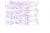
We are testing a 300kW converter made with 12 modules of 25kW in parallel.

Each module has a full bridge of 4 IXFN150N65X2 transistors. The drivers are made with HCPL3120 opto-drivers

We have dangerous oscillations in gate, at frequencies between 40MHz and 50MHz, which increase with voltage and power. We can not eliminate them with ferrite toroidals, and the only one that diminishes its amplitude is to place a RC of 4.7ohms and 10nF between the driver and the mosfet, which excessively increases the consumption of the driver.

In what other way we could improve it?
 

Attachments

  • Driver.png
    Driver.png
    68.9 KB · Views: 85
  • oscilloscope.jpg
    oscilloscope.jpg
    714.3 KB · Views: 82
From a quick look, I'd guess that the gate-drain capacitance is forcing the gate voltage down as the device turns on.
Those FETs do have extremely high inter-electrode capacitance.

Try reducing the series resistor that has a diode across it (R86, in the bottom circuit) - 15 ohms seems rather high for a 2.5A driver; the total series resistance feeding the gate could presumably be as low as 15 / 2.5 = 6 ohms.
It's around 20 ohms total during turn-on at present.

Looking at the data sheet spec for the IXFN150N65X2, figures are based on just one ohm gate drive resistance!

Is the driver supply voltage stable? The 220 feed resistors (eg. R72) seem very high if they actually do have just 3V across them from "+18RP" to 15V for the driver.
That and just a 1uF reservoir cap look wrong, but it may be fine - the only way to tell is with the oscilloscope.
 
Resistance values 15 ohms and 4.7 ohms have been made with the intention of making the turn-ON slower than the turn-OFF, and so reduce the switching noise and ensure the dead time between the upper and lower transistors. The minimum value of 4.7 ohms has been calculated with the intention of not exceeding the maximum 2.5A of the driver.

We agree with the analysis of the resistance of 220 ohms and the capacitor of 1uF. Once we have seen the signals with the oscilloscope, we have increased the capacitor, and we will also modify the value of 220 ohms, which works, but not with a sufficient margin of safety. In any case, the definitive value cannot be determined until we have specified gate resistance values.

We suspect that the problem is caused by the driver's position. The set of 4 drivers is mounted on a small PCB, set with separators on the power PCB. The output of each driver is done with two cables of about 10cm (gate & source) that end in a connector on the base PCB, next to the ISOTOP.

Do you think this could be the cause?

How could the problem be minimized? We have tried to put a 10nF capacitor in parallel with the connector contacts, and reduce oscillations, but this increases the driver's consumption to values too close to the limit indicated in the datasheet
 
The output of each driver is done with two cables of about 10cm (gate & source) that end in a connector on the base PCB, next to the ISOTOP.

Do you think this could be the cause?
Quite possibly. You have 20cm of antenna there to pick up interference, plus significant parasitic inductance and stray capacitance to allow ringing.
 
Last edited:
driver is done with two cables of about 10cm
I have never driven a Gate on long wires. (Have used long coax that is terminated) Try twisting the wires. I think wire inductance is a real problem.
Test if inductance is the problem: Add a small bead to the gate wire, make a loop so the two wires take different paths, these will make things worse. Try twisted wire. Might make things better.

I have never added Gate Source capacitance. If anything I am trying to get rid of capacitance. If adding a capacitor helps that indicates your Gate is wanting a lower impedance driver. (reduce inductance and resistance)

Usually my "Gate Driver" is at the transistor. The Gate Driver needs real good power supply capacitors. Often the Gate wire has 2A or more on the edges. Keep this loop small.
 
If you cannot shorten the cable, split the series resistance between the two ends. That may reduce ringing effects.

You could also try a ferrite core around _both_ wires, to try and ensure the gate-source current is balanced and less influenced by other factors in the overall electronics.

Ideally the dead time control should be earlier in the overall system and not at the driver!
 
Could it be a good idea to replace the cable drivers from the PCB drivers to the base PCB with a coaxial, RG174 or similar type?
 
Status
Not open for further replies.

Latest threads

New Articles From Microcontroller Tips

Back
Top