Continue to Site

Welcome to our site!

Electro Tech is an online community (with over 170,000 members) who enjoy talking about and building electronic circuits, projects and gadgets. To participate you need to register. Registration is free. Click here to register now.

  • Welcome to our site! Electro Tech is an online community (with over 170,000 members) who enjoy talking about and building electronic circuits, projects and gadgets. To participate you need to register. Registration is free. Click here to register now.

Optoisolated Triac Water Heater Controller

Status
Not open for further replies.

Moniker

New Member
Hi All,

First post here. I hope I don’t bore everyone.

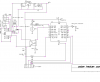
I have just spent some time designing a small water heater controller and would like some help from those with more experience than I have. Mechanical thermostats have too much dead band and this design should provide very little hysteresis. PID controllers are way too expensive and complicated. So, I gave it a shot. I welcome suggestions, constructive criticism, and sage advice. I am sure I did not get it all right.

I am concerned about the wattage of the resistor on the AC side of the Triac. Any help is appreciated.

I calculated the current through an LED that will show the state of the heater. I shot for 5ma but am not sure I got it right.

I shot for 30ma for the IR LED in the optoisolator. Same question there. Did I get it right?

The Triac is a 12A job that I think should get ‘er done with ease. Maybe a heat sink is necessary?

The schematic is attached. I hope you will give it a look and tell me what you think.

Thanks
Moniker
 

Attachments

  • Optoisolated Triac Water Heaater Controller.gif
    Optoisolated Triac Water Heaater Controller.gif
    11.6 KB · Views: 918
I bookmarked this thread just to see what others would say. I think you're on the right track. I didn't verify the specs, but just giving the ckt a quick glance over, it looks fine to me. You might just want to add some power decoupling.
 
I bookmarked this thread just to see what others would say. I think you're on the right track. I didn't verify the specs, but just giving the ckt a quick glance over, it looks fine to me. You might just want to add some power decoupling.

hi D,
I ran a quick sim in LTS, in addition to your recommendation I would suggest some hysteresis and say a 4k7 in series with the inverting pin.
 
Hi All,

I got a few recommendations regarding the circuit I posted. So now I am back with a revised schematic and more questions.

Please take a look and tell us what you think. The questions are on the schematic.

Thanks to all who gave suggestions, especially those who simulated the circuit. I wish I was able to do that.

Thanks All,

Moniker
 

Attachments

  • Zerocross.gif
    Zerocross.gif
    16.2 KB · Views: 562
Hi All,

I got a few recommendations regarding the circuit I posted. So now I am back with a revised schematic and more questions.

Please take a look and tell us what you think. The questions are on the schematic.

Thanks to all who gave suggestions, especially those who simulated the circuit. I wish I was able to do that.

Thanks All,

Moniker

hi,
Do you know you have swapped over the Inv and NonInv inputs on the 2nd circuit.???
This will change the sense of the switching at the output.

EDIT:
As you can see from this image, the heater is switched ON as the water tempr rises.!
The Triac is not not shown only the ZC MOC.
 

Attachments

  • Opto02.gif
    Opto02.gif
    39.1 KB · Views: 491
Last edited:
Eric,

Thank you very much for the pointer.

Yes I previously did connect the sense signal to the wrong input. In the most recent schematic above the sense signal is attached to the +input rather than the -input like in your sim.

I changed that and added a couple other changes. All came from suggestions like yours.

I see that your circuit is not as changed as my most recent one. Is that a mild suggestion from you?

BTW, what software are your using? It seems most capable.

Thank you,

Moniker

hi,
I use LTspice, its free, also the Yahoo Users group has lots of libraries of models.
If you decide on LTS, I could post your 'asc' file, its not easy at first to use LTS, but its a great tool that is well worth the time learning how to use it.
It will save you hours of maths.!

Linear Technology - LTspice IV Downloads and Updates

Those differences are just left overs from the previous.

EDIT:
You do realise with your last circuit the action is the wrong way around..
 
Last edited:
Eric,

Sorry. I sent you a pm with my email address and a reply to see the pm. Then I read your address more clearly and found you do not wish to go that route.

So, since I previously downloaded and installed LTSpice I would surely appreciate it if you could post the appropriate LTSpice file(s) for my use. I am sure the expreience will teach me loads.

Thank you for your patience and help,

moniker
 
Last edited:
Hi All,

Any suggestions for a rail to rail replacement for the 741? That should remove all concerns about saturating the transistor.

Thanks

moniker
 
One thought?--is the water heater 110 or 220v
I have a similar design to implement but am going with a relay instead of a triac
reason = the water heater draws lots of current the one I am going to control has 2-20amp circuit breakers. When an inductance like a heater coil turns on its best to over design. It was suggested to add something like 130% to account for the turn on surge current.
I would be cautious about using a lone triac for this app. The triac will get warm if not hot.
 
here is my overkill schematic

basic design but going to downsize so just going to use a 741 op am instead of PIC
I just want to keep the water temperature at 60-70F degrees
 

Attachments

  • water heater.PNG
    water heater.PNG
    34.8 KB · Views: 311
Hi All,

Any suggestions for a rail to rail replacement for the 741? That should remove all concerns about saturating the transistor.

Thanks

moniker
hi,
Look at this LTS image for the modified circuit, note the resistor changes on the 741 OPA output.

Attached is the 'asc' file, you will need to download the tectriac.lib and the MOX308x.lib, you can get these from the Yahoo LTspice users group, free, just sign up.

If you have a problem with LTS just ask, we will help out.

BTW:
Ref the PM, mines 1932.!, you are still a spring chicken with lots of mileage left in you, go for it....:)
 

Attachments

  • Opto_Htr2.gif
    Opto_Htr2.gif
    40.6 KB · Views: 294
Hi,

I downloaded from the user groupfine. But I am unable to find the 'asc' file. Where is it?

thanks

moniker
 
Hi,

I downloaded from the user groupfine. But I am unable to find the 'asc' file. Where is it?

thanks

moniker

hi,
I will repost it...
 

Attachments

  • opto_htr1.asc
    4.1 KB · Views: 207
A word of caution to anyone planning to use a NTC thermistor as a heat sensor:
if the termistor or its wiring becomes open, then the comparator will think that the water is always cold and will go full blast until the heating element melts down, the water boils or something else (nasty) happens. Believe me, it DOES happen.
All commercial units controlling furnaces or heaters have means to detect open sensor conditions.

To avoid that, you need a second comparator, with a trip point close to Vcc, which will override the first comparator (and probably light up an error LED) and shut-down everything.
 
schmitt,

That is a very good idea. I will try to come up with a plan.

Thansk

moniker

hi,
If you want a fit a 'over heating' detector, you can buy thermostatic cut out switches that mount on the casing of the boiler, this will work even if the electronics dont 'fail safe'.
 
Eric; you are right, redundancy is key to safety.

They can easily implement an open circuit comparator with a dual opamp, plus the thermostatic cut out if everything else fails (i.e. that the TRIAC shorts and allows the full voltage to flow).

If I have time, I can post something later.
 
Status
Not open for further replies.

Latest threads

New Articles From Microcontroller Tips

Back
Top