Continue to Site

Welcome to our site!

Electro Tech is an online community (with over 170,000 members) who enjoy talking about and building electronic circuits, projects and gadgets. To participate you need to register. Registration is free. Click here to register now.

  • Welcome to our site! Electro Tech is an online community (with over 170,000 members) who enjoy talking about and building electronic circuits, projects and gadgets. To participate you need to register. Registration is free. Click here to register now.

Optocoupler connection

Status
Not open for further replies.

Unyhhox

New Member
Greetings gentlemen,

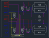
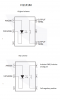
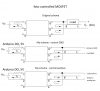
i need an advise with optocoupler connection. I need to switch the negative side of the battery and arduino GND. If i connect it like on the picture attached i get like 40k - 2m ohm resistance on the output so it makes drop voltage to the half. Voltage measurement is the reason i am doing this so drop voltage is very undesirable. Is there a rule the collector must be more positive than the emitter or what am i doing wrong and how to fix it? The link for optocoupler datasheet is below. Battery voltage is 4V.

Optocoupler pdf

All answers and advises are really appreciated.
 

Attachments

  • scheme.png
    scheme.png
    16.5 KB · Views: 118
Normal optocouplers are not rated to pass high currents, they are more for signalling than power control.

You also have to allow for the "current transfer ratio" of the device you use - eg. the TLP621 has a CTR of typically 50% so the output transistor will only turn fully on if the current through it is somewhat less than half the current through the LED.

You really need a DC solid state relay type for power control, or use the opto to switch the gate or base drive to a separate transistor.

eg. something like this (but using a "logic level" FET as you are switching a low voltage:

Or this, with a bipolar transistor - put you load where the relay coil is shown:


Or something like this, which will switch 200mA with a 3mA control signal:
 
Once again .. thank you for your answer.

Voltage measuring is just signal isnt it? But dont know how much current flows in the curcuit. I tried to add resistance to the curcuit to get 9mA which is maximum transfer ratio for TLP621 ... i measured 60kohm on the output anyway.

Also .. what is the load.. the arduino? if i connect negative side of a battery to GND of an arduino? Arduino has its own external power supply.

That ASSR seems interesting .. what is the actual difference between optocoupler and assr?

Looking forward to your answer.
 
It appears from the circuit that you originally posted, that you are trying to switch the power supply (or battery) that runs an Arduino module?

As Mike says, what exactly are you trying to switch??

The "load" is whatever the switch item is passing power for; it could be just a tiny current through a resistor for a logic signal, or controlling full power for something.
 
Sorry guys, my bad. I should have explained my curcuit first. I attached my schematic below. It is DIY balancer module for 4S battery. This is just for 2S. This cuircuit should measure the voltage of each cell (1 and 2) and in the case of exceeding over 4V, while charging, the mosfets (mos1,mos2) should turn on and the additional energy put into the power resistors (paralel rez1, rez2). When all cells are 4V the charging is interrupted. Accurate measurement is required for realization this project ... the accuracy of 0.01 atleast. As you probably know the arduinos maximum voltage is 5V so i can measure first cell and need a voltage divider to measure the others (8,12,16V). I tried to measure accuretly with voltage dividers but it is not easy to optimize the software for this .. dont even know if it is possible. So i decided to try different approach. Positive sides of all cells are constantly connected to the arduino (analog inputs) and only one cell´s negative side is connected at the time so GNDs of all cells are not shared (you know, what would happen). So arduino would send a signal to optocoupler to connect GND arduino with negative side of first cell, analog pin would measure the voltage and hold that value, after like 0,2s would disconnect GND of first cell and connects negative side of the second cell, analog pin would measure the voltage, hold the value etc etc. The values should update every second so circa 0,2s for each cell with time reserve. All values are gonna be shown on display. The connecting path resistance between negative cell side and arduino GND should be as low as possible to eliminate drop voltage.

Sorry for my english. Hopefully it is understandable.

Looking forward to your answers guys. Thanks
 

Attachments

  • scheme.png
    scheme.png
    36.5 KB · Views: 95
It looks like you really need an analog switch to do it that method; a bipolar transistor is not ideal.

Also note that you cannot safely force the analog inputs on an MCU outside of the supply range limits. With that configuration, if you ground the negative of the lowest cell in a four cell pack, the ADC pins will have roughly 4, 8, 12 & 16V on them...

Personally, I'd use a differential amp to measure each cell voltage and adapt it to ground referenced.
eg. https://en.wikipedia.org/wiki/Differential_amplifier#Operational_amplifier_as_differential_amplifier
R1=R2; RF=RG. As long as the ratio of input to feedback resistors keeps the op amp inputs within common mode range, the circuit inputs can be far beyond the supply.

For an optically isolated analog switch type device, look at the H11F1 or similar.
 
Holy crap i missed that .. you are right. So i will have to disconnect a positive and also negative side of the cell before arduino starts connecting and measuring the other. I have absolutely no idea how to work with amplifier so i would like to stick with optocoupler or ASSR. ASSR is opto controlled mosfet so basically optocoupler able to handle bigger loads right?

That H11F1 is optocoupler or it is not? i do not see a difference between this one and TLP621.

Thank you.
 
That H11F1 is optocoupler or it is not? i do not see a difference between this one and TLP621.

The H11F1 is an optocoupler, but the output device is a special FET rather than a bipolar transistor.
In effect, it becomes a low-value resistor when on, that can conduct both ways and is also not polarity sensitive when off.

A bipolar transistor only conducts in one direction when on and requires a fixed polarity, so is not good for passing varying voltages, as you need.
 
Ah, understood. So i might use MOSFET as well as FET right? What about

MOSFET

If i put 5V on the input with 370R resistor and use connection C, i might get 5-10 ohm resistance on the output right? There is + connected to pin 6 and - to pin 5. What should i connect to which pin? Negative cell side to + and GND arduino to - or the other way? Or negative cell side to -, arduino to + and positive side to + and arduino to -?

Thank you for your valuable advice.
 
Sorry, I cannot follow that description.

I was thinking that the H11F1 optos could be used directly as the "switch" parts to connect the Arduino 0V and ADC to a particular cell - and +

The MOSFET opto device you link to is more a power switch, it may not work to pass low voltages with precision, as you need to measure cell voltages.
 
I read datasheet of that MOSFET again and there is mentioned "Controls low-level analog signals" so it should work? I decided to test both and will see which one is better. I attached schematic of mosfet and H11F1 how would i connect it. .. is it correct? Thank you
 

Attachments

  • dsh.523-172.1.pdf
    265.6 KB · Views: 112
  • H11F1M.png
    H11F1M.png
    65.4 KB · Views: 107
  • MOSFET.png
    MOSFET.png
    57.1 KB · Views: 113
Status
Not open for further replies.

New Articles From Microcontroller Tips

Back
Top