Continue to Site

Welcome to our site!

Electro Tech is an online community (with over 170,000 members) who enjoy talking about and building electronic circuits, projects and gadgets. To participate you need to register. Registration is free. Click here to register now.

  • Welcome to our site! Electro Tech is an online community (with over 170,000 members) who enjoy talking about and building electronic circuits, projects and gadgets. To participate you need to register. Registration is free. Click here to register now.

Opto Isolated RS232 - TTL Help

Status
Not open for further replies.

samltd

New Member
Hi,
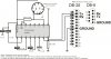
I want to conect my camera to computer. I've read that camera uses TTL signals, while serial PC port uses +/-12V. So I built this adapter. So far it works, but it doesn't provide protection. That's why I tried to build an opto-isolator. I found 2 diagrams using optocouplers but I don't know how to use them.

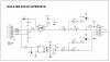
Opto Isolator 1 seems to be the most convenient, I have the PCB diagram, component layout, component list and most important I can order the PCB very cheap. But the power supply is giving me hard time.

"Power to the PC side of the circuit is derived from the signal lines DTR and RTS. Positive supply is derived from RTS and negative one from the DTR line, therefore it is necessary for the user program to set the RTS status to logic zero & DTR to logic one in order to get the proper supply levels at the output.

How can this be put in practice? How can I make the adaptor using just the power from PC and camera?


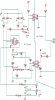
Opto Isolator 2 is more complicated because I have just the picture of layout.
In addition I understand from this that a suplimentary power source must be added to the camera side.

Any suggestion is very appreciated. Thanks
 

Attachments

  • PC Adaptor.jpg
    PC Adaptor.jpg
    91.9 KB · Views: 4,163
  • Opto Isolator 1.jpg
    Opto Isolator 1.jpg
    98.1 KB · Views: 6,501
  • Opto Isolator 2.jpg
    Opto Isolator 2.jpg
    134.7 KB · Views: 3,222
There is no need for such elaborate "protection".
Level shifting is very commonly done with a MAX232 chip or some variant thereof.

Most of the time a computer's serial port can take in 0 to 5v signals ok. And most devices such as your camera are made to accept 0 to 5v signals.

It would be hard to make an optoisolator run as fast as a serial port might go.
 
RS232 Surge protection

I have already this kind of circuit using MAX232.
My idea is to protect the camera from any power surge or spike coming from power lines thru PC.
Even the data transfer speed will be slower, this is not an impediment.

Please explain this:
"Power to the PC side of the circuit is derived from the signal lines DTR and RTS. Positive supply is derived from RTS and negative one from the DTR line, therefore it is necessary for the user program to set the RTS status to logic zero & DTR to logic one in order to get the proper supply levels at the output."
How can this be made?
 
Opto Isolated RS232 - TTL - Nobody knows?

Please explain this:
"Power to the PC side of the circuit is derived from the signal lines DTR and RTS. Positive supply is derived from RTS and negative one from the DTR line, therefore it is necessary for the user program to set the RTS status to logic zero & DTR to logic one in order to get the proper supply levels at the output."
How can this be made?
Nobody knows?
 
sam...
optical isolation is used when circuits are powered from different supplies. if your camera is powered from battery, you won't need this (it sure doesn't hurt). if your camera is not battery powered (uses power supply) and PC is also connected to AC (not a laptop running on batteries), you could use optical isolation.
btw. your first circuit is NOT optically isolated. it's just level shifter... you can modify it by adding optocouplers (you can get version that has TTL driver output, not just transistor).
stealing power from port is not a good idea. while it can work, it is not something you want to rely on, specially that RS232 ports are endangered species, most new computers don't even have them and those that do are increasingly moving to low power (les power can be stolen from port). stealing power from port is simple enough. port has few handshake lines which are sometimes not used (none of the three circuits you posted uses them). by switching these lines, one can produce signal that can be used to power devices. now the PC software that communicates with the camera need to take control over handshaking lines and force them into particular state(s) to produce those signals.
but think about it, one such circuit is already in your PC. you expect that circuit to provide enough power to run another such circuit. search for simple PIC programmers that ware stealing power from port and you will see that while they can work, this is the most common problem when they don't work.
RS232 spec says that proper signal for "0" is +3..+25V and "1" is -3..-25V.
Well that used to be... In the old days PCs used internal +/-12V supply to power ports (and provide enough juice that could be stolen, I was getting some 25mA from my oldest PC). nowdays with energy saving, low power devices etc., you are lucky to see +/-5V. i didn't check how much current one can get out of RS232 port on a newer computer but i bet it is much less.
Take a look at the USB<>RS232 converters. They are all low power devices that will have hard time powering external circuit (unless circuit is very low power). but you can hack it (open DB9 cover and replace it with larger one so your TTL shifter fits in). this way you get your RS232 signals and you can get the 5V power for shifter circuit (and optocouplers if you want). and phisically it's USB port you will be using...
 
Last edited:
Status
Not open for further replies.

Latest threads

New Articles From Microcontroller Tips

Back
Top