Continue to Site

Welcome to our site!

Electro Tech is an online community (with over 170,000 members) who enjoy talking about and building electronic circuits, projects and gadgets. To participate you need to register. Registration is free. Click here to register now.

  • Welcome to our site! Electro Tech is an online community (with over 170,000 members) who enjoy talking about and building electronic circuits, projects and gadgets. To participate you need to register. Registration is free. Click here to register now.

opto isolated h bridge PCB design

Status
Not open for further replies.
With that circuit, the options seem to be full speed either way or brake - I.E. motor shorted.

Also, isn't 10k a little high as it has to charge the bottom gates when the opto is off.

Mike.
 
"I don't think the design above lends itself to PWM." sorry i didn't understand this.
When one side is on, the motor turns one way... When the other is on, the motor turns the other.. If when they are both on it free wheels, then PWM may work... If when they are both on the motor brakes ( stops quick ) then PWM wont work..
 
I tried the last circuit
When giving: high low low the motor turns in the first direction
When sending: low low high the motor turns in the other direction
But the speed of the motor is very low, i measured the voltage and found it less then 1 volt.
 
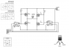
this is the circuit i have now
when i try simulating it with Proteus (adding and Arduino UNO in place of inputs, and a motor in output) i get this errors:
[SPICE] transient GMIN stepping at time=2.54501e-005
[SPICE] TRAN: Timestep too small; timestep = 1.25e-019: trouble with node #00000.

and i'm still having the problem of low voltage, i tried both with 5v and 9v in source bit i get always low than 1v.
 

Attachments

  • optisolatormotor.BMP
    88.9 KB · Views: 201
  • optisolatormotor_wthout arduino.BMP
    7 KB · Views: 180
In your schematic, Q2 and Q4 are upside down..
that was the problem!
thank you very much
the circuit is now working

what about pwm?
i just add it like the 1st circuit?
and when i should use it (with low low low ?)
 

Attachments

  • optisolatormotor.png
    optisolatormotor.png
    26.8 KB · Views: 205
How much current is the motor taking... The original circuit had a PWM controlled ground.... That means another optocoupler..

To check if you can use PWM on the inputs.... Take both optocouplers high ( high low high ) and see if you can turn the motor by hand easy.. If not it's on brake... Then try low low low and see if you can turn the motor by hand...

Or the way the original should have been.
upload_2018-1-13_20-43-23.png
 
Status
Not open for further replies.

Latest threads

Back
Top