earckens
Active Member
Hi,
a project requires detection by optical means of the presence of objects.
Design requirements:
1. any Vcc between 5Vdc and 18Vdc
2. use of LDR sensors
3. 4 channels
4. detection independent of ambient light
5. TTL HIGH level when detection occurs
6. relay activation when detection occurs, per channel
7. 4 separate channels but with possibility to gate any of channels 2, 3 or 4 in OR gate to the first detector output channel 1
8. rising edge detection time to be delayed by Time Constant 1 (LDR + C2, 4, 6, 8): when detection occurs LDR value increases
9. falling edge detection time to be delayed by Time Constant 2 (LDR + C1, 3, 5, 7): when detection stops LDR value decreases
10. LED indication of detection present, per channel
11. Time Constant 1 < Time Constant 2
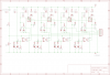
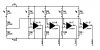
I based my project on a little diagram attached here as well.
Please scrutinize my little own schematic, any feedback is greatly welcomed.
I use p-channel MOSFET because only the last few days did I learn it would be better to use n-channel and I already had a draft ready; but my inertia to follow the road of least resistance made me finish this diagram with a p-channel. Unless there are compeling reasons to change to n-channel..
Thanks for your feedback,
Erik
EDIT: some minor cosmetic changes in the Eagle schematic
EDIT2: requirement 5 changed to TTL HIGH level when detection occurs
EDIT3: improve my english in the text
a project requires detection by optical means of the presence of objects.
Design requirements:
1. any Vcc between 5Vdc and 18Vdc
2. use of LDR sensors
3. 4 channels
4. detection independent of ambient light
5. TTL HIGH level when detection occurs
6. relay activation when detection occurs, per channel
7. 4 separate channels but with possibility to gate any of channels 2, 3 or 4 in OR gate to the first detector output channel 1
8. rising edge detection time to be delayed by Time Constant 1 (LDR + C2, 4, 6, 8): when detection occurs LDR value increases
9. falling edge detection time to be delayed by Time Constant 2 (LDR + C1, 3, 5, 7): when detection stops LDR value decreases
10. LED indication of detection present, per channel
11. Time Constant 1 < Time Constant 2
I based my project on a little diagram attached here as well.
Please scrutinize my little own schematic, any feedback is greatly welcomed.
I use p-channel MOSFET because only the last few days did I learn it would be better to use n-channel and I already had a draft ready; but my inertia to follow the road of least resistance made me finish this diagram with a p-channel. Unless there are compeling reasons to change to n-channel..
Thanks for your feedback,
Erik
EDIT: some minor cosmetic changes in the Eagle schematic
EDIT2: requirement 5 changed to TTL HIGH level when detection occurs
EDIT3: improve my english in the text
Attachments
Last edited:

