Continue to Site

Welcome to our site!

Electro Tech is an online community (with over 170,000 members) who enjoy talking about and building electronic circuits, projects and gadgets. To participate you need to register. Registration is free. Click here to register now.

  • Welcome to our site! Electro Tech is an online community (with over 170,000 members) who enjoy talking about and building electronic circuits, projects and gadgets. To participate you need to register. Registration is free. Click here to register now.

operational amplifier transfer function & simulator

Status
Not open for further replies.

dark

Member
Hello Forum,

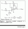
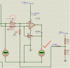
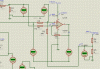
I just did a simple simulation with proetus , an saw the gain stage wasnt working . The transfer function I calculate is Vout={(V1-V2)*(R7/R3)+1.25v(R8/R6)} . Now when I simulate the result is = 3.66v , whereas it should be 4.92V . Have I done something terrible please advise.

Thanks
 

Attachments

  • sub.GIF
    sub.GIF
    23.2 KB · Views: 293
Last edited:
It's not terrible, but the simulation is correct, it's your equations that are incorrect. A simple way to look at it is that the 1.25V REF is, in effect, your common reference for the differential amp connection, which gives it a gain of +1 to the output. This offsets the output by 1.25V. Thus the output voltage is simply the differential signal gain of the two input signals plus the offset, or (V1-V2) * (R7/R3) + 1.25v = 3.67V, close to the 3.66V you simulated.
 
It's not terrible, but the simulation is correct, it's your equations that are incorrect. A simple way to look at it is that the 1.25V REF is, in effect, your common reference for the differential amp connection, which gives it a gain of +1 to the output. This offsets the output by 1.25V. Thus the output voltage is simply the differential signal gain of the two input signals plus the offset, or (V1-V2) * (R7/R3) + 1.25v = 3.67V, close to the 3.66V you simulated.

In order to get a general expression for the full transfer function for this circuit, I've replaced the 1.25V reference by a variable V3. Then the correct transfer function for this circuit is:

Code:
     R8(R3+R7)         R7          R6(R3+R7)
V1* ----------- - V2* ---- + V3* ------------
     R3(R6+R8)         R3          R3(R6+R8)

Which gives a value of 3.69 V at the output.

It isn't quite true to say without qualification that:

"...the 1.25V REF is, in effect, your common reference for the differential amp connection, which gives it a gain of +1 to the output."

It happens to be true for the particular values of the resistors because they make the coefficient of V3 in the transfer function equal to 1. It isn't just because "...the 1.25V REF is, in effect, your common reference for the differential amp connection" for this topology, without consideration of the actual resistor values.

If other values for the resistors had been chosen such that the expression:

Code:
  R6(R3+R7)
------------
  R3(R6+R8)
had a value other than 1, then the gain of the 1.25V REF wouldn't be +1, since that expression is in fact the gain of the 1.25V REF to output.
 
My qualification (perhaps not explicitly stated, but noted) was that this was a (standard) differential amp connection, which I assumed was the intended configuration. A standard differential amp connection using an op amp is one in which the ratio of R6/R8 equals the ratio of R3/R4 (typically R3=R6 and R7=R8). That is what makes the connection at the bottom of R8 the common point with a gain of 1 to the output.

Of course my statement is not true for any arbitrary value of resistors, but it is true for a differential amp connection.
 
Dark doesn't have your level of knowledge, I suspect.

You made a statement without any analysis to show why it is so. It may be something that you (and I) have known for years, but it seemed to me that because of the way you put it, a neophyte might have thought that it was a property of the topology, without consideration of the resistor values.

I think it's good to keep in mind the apparent experience level of the person asking a question, who, in this case, didn't get the transfer function right.

That's why I offered a more detailed explanation.
 
Hi ,
Thanks for the reply . I checked The Electrician equation but my simulation and calculation varies . I used R6=80k ,R3=50k, R8=R7=200k . The gain comes out to be '(3.72 * ((200 * (50 + 200)) / (50 * (80 + 200)))) - (2.5 * (200 / 50)) + (1.25 * ((80 * (50 + 200)) / (50 * (80 + 200)))) = 5.07142857
'5x as per The Electrician whereas the simulated is 1.3x? .

Even if as crutschow says the subtractor sesults by equating the resistors , the gain stage still holds . Please see the attached ;
sub2-gif.26855


here I should be getting a gain of 2x as per 200k(for R7 and R8)/100k(for R3 and R6)=2 .

I get this ;
sub3-gif.26856


which shows a gain of 1.3x3.72V=4.94V . Can you please explain with some example to sort the discrepancy.

Thanks for your time.
 

Attachments

  • sub2.GIF
    sub2.GIF
    7.6 KB · Views: 1,175
  • sub3.GIF
    sub3.GIF
    23.7 KB · Views: 1,141
Last edited:
Could you re-run your simulation with a voltmeter attached to pin 5 of the opamp and another one connected to the junction of R4 and R5?

What is the voltage at the top or R4, and where does it come from? I don't see a voltage source attached there.

Also, expand your display of the simulation a little to the left so we can see the voltmeter attached to V2.

It looks to me like the formula for Vout in Figure 6 has the wrong coefficient for Vref.

Hi Electrician ,The voltage on the top of R4 is from a 10V voltage source. In reality its going to be an REFERENCE IC.

Here is the simulation as you asked for;
sub4-gif.26857


I have noticed that the equation holds true when the reference 1.25v at the non inverting pin is removed and its grounded , it this an ISIS bug?.
Thanks
 

Attachments

  • sub4.GIF
    sub4.GIF
    35.1 KB · Views: 1,167
If I set Vref to 1.26528 instead of 1.25, and set V2 to 2.54 instead of 2.50, then recalculate the transfer function I gave in my first post, I get Vout = 4.933257.

If you sense the voltage at V2 with more digits, and put that number in the formula, you'll probably get what the simulation gives you.

I do this to your equation;
(3.72 * ((200 * (50 + 200)) / (50 * (80 + 200)))) - (2.54 * (200 / 50)) + (1.26528 * ((80 * (50 + 200)) / (50 * (80 + 200)))) = 4.93325714

But couldnt see any substantial change in the gain form 5.01 something to 4.933 can you please paste your calculation. I have in my mind that the virtual GND is getting disturbed with reference of (1.25V) . If I ground this 1.25V reference I do get a required gain . BUT not with the reference what could be the reason? .
 
Oh My , sorry for calling Vout as gain above . It looks ok with those decimal places , thanks . I wanna ask if MIcrochip spec Figure 6 transfer function correct.

Regards
 
The coefficient of Vref is wrong. I should be just 1. In other words, just add in Vref. Don't multiply it by R2/R1.

Thanks Electrician for the details . I hope the Microchip people will never rectify the error as the Texas Instrument people does with their specs.

Thanks
Adi
 
Status
Not open for further replies.

Latest threads

New Articles From Microcontroller Tips

Back
Top