Electro Tech is an online community (with over 170,000 members) who enjoy talking about and building electronic circuits, projects and gadgets. To participate you need to register. Registration is free. Click here to register now.
Welcome to our site! Electro Tech is an online community (with over 170,000 members) who enjoy talking about and building electronic circuits, projects and gadgets. To participate you need to register. Registration is free. Click here to register now.
I am trying to make a signal of .5mv to 10v. Is there any opamp or any cicuit that anyone recommends for this? I have tried a curcuit, but it seems the gain cannot go past one.
I am trying to make a signal of .5mv to 10v. Is there any opamp or any cicuit that anyone recommends for this? I have tried a curcuit, but it seems the gain cannot go past one.
The gain of an opamp circuit is simply set by the feedback around it (essentially two resistors) - try googling for 'opamp tutorial' and doing some reading!. If you've tried a circuit, then post it!.
You also need to give more details, so far it's lacking in enough information to give an accurate answer!.
Yea i have been reading....just that i am a little confused as to wether a single opamp can give mee a 'googd' 2000 gain.
i was thinking of perhaps 3 10gains with a 2 gain.
Op-amps have a huge gain which lately seems to be around 100 dB or so. THis allows you to use a few "infinite" gain approximations when designing your feedback loop to reduce the gain to something useful (like two). Since 2000x is really small compared to 100dB, the approximation should still work...and you shoul be able to pull it off fairly easily.
But the real problem (I think) is that 2000 gain is a large gain compared to the maximum output of the op-amp (say 5V or 12V) that, in order not to saturate the amplifier, the signal would have to be less than 1-2mV on average/maximum. The SNR could be too small and noise could distort (or drown out) your input signal.
With a gain of 2000, an old, old 741 opamp will have its output full of noise like Dknguyen said. Its frequency response would drop above only 200Hz. A modern wide bandwidth opamp like a low noise TL071 would still reduce the output above only 3kHz.
Two stages each with a gain of 45 would be able to reach up to higher than 20kHz with TL072 dual opamp. The noise would still be audible unless opamps with extremely low noise were used.
Well, what i am doing is taking ouput signals from a load cell, and the max ouput i think could be 2-4mv. Then i try to amplify this signal to a range of 1- 10v that will be read by another piece of equipment. The opamps i would most probable use is the 741s.
Well, what i am doing is taking ouput signals from a load cell, and the max ouput i think could be 2-4mv. Then i try to amplify this signal to a range of 1- 10v that will be read by another piece of equipment. The opamps i would most probable use is the 741s.
PSA... DON'T use a 741 for this.... Load cells bascially work at DC, since they don't change much over time (at least the one's I've used). They are used to measure the weight of silos etc.
For your application, you need a LOW noise amplifier, with huge common mode rejection, pitfalls of most load cell applications. So what do you use? Go to Analog Devices or Burr Brown and check out their instrumentation amplifiers. These will give you superb common mode rejection, and low noise. They won't give you a gain of 2000, but that's okay. I've seen instrumentation amps with a gain of 1000, then you can follow that up with a basic op amp circuit to get to 2000, or whatever else.
His load cell in another post (I wish people would keep one topic in one post) has fast moving trucks over it and he wants to weigh them while they are flying.
His load cell in another post (I wish people would keep one topic in one post) has fast moving trucks over it and he wants to weigh them while they are flying.
Then bandwidth would be a consideration. In either case, I would still recommend an instrumentation amp, albiet with an eye on the rate of change on the input.
I have got a AD620A to amplify the output. But the inamp output wave form i get is a half wave sine. When i used a 741s to make a homebrew inamp, i also got a half sine wave i dun think its the load cells signal, but also i cant check, the schools equipment cant check the small signal. The output from the load cell seems to be riding on the half wave sine.
I think the noise is very high and the ammeter reading i get when not connected to anything are even higher that our load cell output. I was told by thet lab tech that the power supply's ground is not a true ground. So i did not ground the load cell. However, when i did, the output from the inamp changed, the half sine waves decreased in amplitude, and also the output will also turn into an almost straight line when i step on the load cell.
I also tried connecting a capacitor parallel to the load. But, the whole output turns to a negative and wont even react to the load cell output.
So how can i reduce the noise(im not sure if it is noise, but the amplified outputs have half waves, i am thinking of low pass filters but im not sure)? Also any comment on setting the gain for the device? Thanks.
Still no schematic for us to see.
Are the inputs from the sensor balanced and with a shielded cable? If not balanced and shielded then your circuit picks up mains hum.
Are the inputs from the sensor balanced and with a shielded cable? ?? Balanced??? The cable is shielded, and i connected the shield to the power sources ground. Then also theres still the problem with the instrumental amp...i can only get a 'following' output if i short it as in the diagram. When i try a trimmer or even a fixed resistor in between, it dosent work.
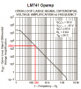
The top right shows the waveforms... black is when i do nothing. Green is when i step on load cell. red is when i try a capacitor across as in the diagram. I think its a polar cap.. but then even when i try reversed still the same.
I don't think AD620 is meant to be run open loop, which is what you are doing when you make Rg=0. A gain of 1000 (Rg~49) is the highest mentioned in the datasheet. With Rg=0, the gain is unpredictable (theoretically infinite).
AD620 does not have differential outputs, as shown in your schematic. Perhaps you think pin 5 is the output "reference"? Pin 5 should normally be grounded.
If you try these things and are still having problems, post your results here.
I tried using pin 5 as refernce for my load..it seems to be working. But the waveform looks funny. If like you say, i ground pin 5, then where do i get the reference for my load? I tried putting the load to ground. dosent work... Or do i make a own reference with some voltage divider or just loop it from the load cell reference?
I tried using pin 5 as refernce for my load..it seems to be working. But the waveform looks funny. If like you say, i ground pin 5, then where do i get the reference for my load? I tried putting the load to ground. dosent work... Or do i make a own reference with some voltage divider or just loop it from the load cell reference?
I tried using pin 5 as refernce for my load..it seems to be working. But the waveform looks funny. If like you say, i ground pin 5, then where do i get the reference for my load? I tried putting the load to ground. dosent work... Or do i make a own reference with some voltage divider or just loop it from the load cell reference?
The output of AD620 is referenced to whatever is on pin 5. This could also be the reference to your load. As long as this reference is between the two power supply rails you provided ot the part, there is no issue. when you say you grounded the load (also = pin5), and it didnt work, what do you mean?
Is your load that resistor and capacitor in parallel? (from your diagram)
What are there approximate values? Generally, you should not be driving very large capacitors (more than say 100pF)directly and the load resistor cannot be too small or the AD620 cant drive that either. If you need to drive a small resistor load (high current), you need to add a power stage.
Best if you elaborate on these points.
Also, I would suggest using a low noise inst amp as the first stage and put most of the gain (within reason) and then follow it by 2 or more low noise stages to get up to 2000. Bandwidth requirements need some calculations.
As a caveat, if Ref is not GND, it would not be advisable to connect a scope GND to it. If you left it floating except for the scope GND connection, it could account for the hum you are seeing. If you connect it to a voltage (why would you?), a scope GND could short out the supply.
This site uses cookies to help personalise content, tailor your experience and to keep you logged in if you register.
By continuing to use this site, you are consenting to our use of cookies.

")