Electro Tech is an online community (with over 170,000 members) who enjoy talking about and building electronic circuits, projects and gadgets. To participate you need to register. Registration is free. Click here to register now.
Welcome to our site! Electro Tech is an online community (with over 170,000 members) who enjoy talking about and building electronic circuits, projects and gadgets. To participate you need to register. Registration is free. Click here to register now.
Av=(1+(Rf/Rr)) where Rf is the feedback resistor, and Rr is the "reference" resistor
Rf is 700k, Rr is 10k, so Av=71. you have a slight voltage drop on the input divider of about 5% so Vout is 71*(Vin*0.95) but limited by the bounds of 0V, 5V (if it's a rail-to-rail op amp)
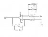
This circuit can be analyzed using what is called "Nodal Analysis" or just simply voltage divider theory.
To start, we can replace the op amp with a voltage dependent voltage source with arbitrary gain A. We can make A infinite later for an ideal op amp and that is often how these circuits are analyzed.
Next, we would lump the R's and C's in parallel to make a single element with impedance Z1 and Z2 for example. Using vp for the non inverting terminal and vn for the inverting terminal, we would then develop equations for these two vp and vn.
Having those equations, the output voltage Vout is then equal to:
Vout=A*(vp-vn)
and we would solve that for Vout.
We could then let A go to infinity, or alternately if we want A to be infinity (often the case) we can set vp=vn and simplify. What we end up with is a frequency equation for Vout. We then solve that for sinusoidal waves by replacing each s with j*w, then simplify and solve for the amplitude. Once we have the amplitude we can plot the response or we could solve for the point where the response is 3db down and that gives us the cutoff frequency. We can also solve for the phase shift if we'd like to see that, then plot that too.
Because of the C's the response is frequency dependent, and looks like this:
Vout=(Vin*R388*sqrt((R389+R387)^2+w^2*C380^2*R387^2*R389^2))/(R387*sqrt((R388+R386)^2+w^2*C389^2*R386^2*R388^2)*sqrt(w^2*C380^2*R389^2+1))
where
C3800 has been changed to C380 for a little simplicity.
We can note that all the w^2 are under the radicals, so it looks surprisingly like a first order response. Since there are so many values that are the same, we can simplify this further by making the following changes:
R389=R388
R387=R386
C389=C380
and that gives us a much more simple output equation:
Vout=(Vin*R388)/(R386*sqrt(w^2*C380^2*R388^2+1))
and this is clearly a first order response, which is a little unusual for a circuit with two capacitors in it because this entire circuit is equivalent to a single RC low pass filter followed by a amplifier with a gain of 20 except for the input impedance.
The phase shift is also the same as a first order filter, so we have basically a first order low pass filter with gain, so the cutoff frequency is w=1/RC as someone else mentioned, and the gain is 20.
We could look at this in more detail if you wish. A prerequisite is understanding complex numbers and complex algebra.
Sorry, but that's not quite right. The gain would be 21 if we applied the signal directly to the non inverting terminal, but since we have a voltage divider there too the gain of that divider is:
G1=200/210
and the gain due to the other divider is G2=200/10=20 so the overall gain is:
G=G1*(1+G2)
so
G=200/210*(21)=200/10=20
So the gain is 20. I had mentioned this in post #5 as well.
Of course this is a low pass filter so the response follows that of a low pass RC filter with an added gain of 20.
This site uses cookies to help personalise content, tailor your experience and to keep you logged in if you register.
By continuing to use this site, you are consenting to our use of cookies.