Continue to Site

Welcome to our site!

Electro Tech is an online community (with over 170,000 members) who enjoy talking about and building electronic circuits, projects and gadgets. To participate you need to register. Registration is free. Click here to register now.

  • Welcome to our site! Electro Tech is an online community (with over 170,000 members) who enjoy talking about and building electronic circuits, projects and gadgets. To participate you need to register. Registration is free. Click here to register now.

OP AMP Questions

Status
Not open for further replies.

Suraj143

Active Member
1676286985106.png


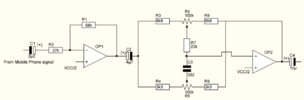
1) Can I share the VDD/2 Vref point with another OPamp? Or do I need to add another resister divider & give to the other OPAMP seperately?

2) What will be happen if I give the wiper pin of volume controller to OPAMP side & take one corner pin to power amp?Or my drawing is correct?
 
You can share the Vref as long as it's also to a point that does not have any feedback connections, as with the circuit you show.

The opamp inputs should take next to no current so not affect the reference voltage by any significant amount.

If you were going to connect it to circuits that had varying voltages, then you would need to buffer it with an opamp to give a stable voltage that could source or sink some current without affecting the voltage.

The volume control is drawn correctly. If the wiper was to the opamp, it would be shorting out the opamp signal out when turned all the way down.
 
You can share the Vref as long as it's also to a point that does not have any feedback connections, as with the circuit you show.
In the drawing I did not show the Gain resistors (feedback resistor from amp out to inverting input & the other resistor from inverting pin to gnd).I have both resistors (gain set to 2).

In a pre amp if we consider stereo in a single opamp package we have two opamps built in. So do I have to add two seperate voltage dividers? in a single opamp package IC?
 
In a pre amp if we consider stereo in a single opamp package we have two opamps built in. So do I have to add two seperate voltage dividers? in a single opamp package IC?

No, one divider can feed the bias to both OpAmp NI inputs.

1676299508830.png


Regards, Dana.
 
Last edited:
If the wiper was to the opamp, it would be shorting out the opamp signal out when turned all the way down.
Also, depending upon the impedance of the amp input to the pot, the output voltage will likely not vary much with pot wiper position until it shorts the op amp output.
 
Many Thanks.

If I have another opamp for (Tone control stage) can I also share the Divider point (Vcc/2) to feed Inverter Input in this opamp?
The + input of an inverting opamp draws an extremely low current (see its datasheet). Then the voltage divider can bias many inverting opamps.
 
If I have another opamp for (Tone control stage) can I also share the Divider point (Vcc/2) to feed Inverter Input in this opamp?
No..
The inverting input bias would draw current, depending on the opamp output voltage.

For that, you need to buffer the bias voltage - eg. connect the divider to the + input of a spare opamp, then connect the - input to the output, so it is forced to match the divider voltage.

The output is then a much lower impedance that will hold the voltage when some current id drawn (as long as it is not excessive).
 
An inverting opamp in a tone controls circuit has its inverting input resistor capacitively coupled and its non-inverting input that has very low current connects to the bias voltage divider.
Here is an inverting tone controls opamp:
 

Attachments

  • tone controls.png
    tone controls.png
    12.8 KB · Views: 129
No..
The inverting input bias would draw current, depending on the opamp output voltage.

For that, you need to buffer the bias voltage - eg. connect the divider to the + input of a spare opamp, then connect the - input to the output, so it is forced to match the divider voltage.

The output is then a much lower impedance that will hold the voltage when some current id drawn (as long as it is not excessive).
The input bias current of a grunge OpAmp is typically << 1 uA, a LM324 is 60nA hot, so
drawing current thru a 10K divider would generate << 1 mV.

No need to use an OpAmp as a buffer for this problem.


Regards, Dana.
 
An inverting opamp in a tone controls circuit has its inverting input resistor capacitively coupled and its non-inverting input that has very low current connects to the bias voltage divider.
Here is an inverting tone controls opamp:
The Inv input draws its bias from the output in that tone control circuit.
So in practice, rightfully, its DC coupled. But to your point the two port
is AC coupled input signal path at its input to the tone control network.

Regards, Dana.
 
Some more doubts refering my below schematic...!!

1)How is the polarity of my input capacitor ?
2)Do I need the C2 capaciotor?
3)Do I also need that output 100R resistor?

1676335801348.png
 

Attachments

  • 1676335696381.png
    1676335696381.png
    44.9 KB · Views: 128
3) R10 is used to decouple C load from OpAmp output which can cause it to be unstable.
However if the other side of C4 is connected to a high z input then yes you could
eliminate it. But if rest of system is DC offset then you need to keep C4 in place because
it otherwise would create a DC offset beyond the bias supply causing waveform to
bang into rails. Try it with and without and look at output with a scope for both
cases. You can do the case with, store that waveform, then without, recall waveform
to overlay it with latter and compare results.

2) C2 is used to decouple DC into following stage. Prevents DC from getting gained up
in the following stager and cause distortion with output no longer centered around the
bias supply.

1) C1 same as C2. Prevent any DC from phone from.......(same as above). Polarity, should
be OK.


Regards, Dana.
 
Last edited:
Some more doubts refering my below schematic...!!

That circuit shows the bias connections are only to the non-inverting inputs; those do not need buffering as there is no signal feedback to those inputs.

Your post #8 said you were using it for an inverting input bias, which would then have needed buffering; that's the confusion.
 
Status
Not open for further replies.

Latest threads

New Articles From Microcontroller Tips

Back
Top