Continue to Site

Welcome to our site!

Electro Tech is an online community (with over 170,000 members) who enjoy talking about and building electronic circuits, projects and gadgets. To participate you need to register. Registration is free. Click here to register now.

  • Welcome to our site! Electro Tech is an online community (with over 170,000 members) who enjoy talking about and building electronic circuits, projects and gadgets. To participate you need to register. Registration is free. Click here to register now.

op-amp input bias current

Status
Not open for further replies.

mandeep79

New Member
Hi,
I am from computer science background and very new to electronics specially analog electronics. If I ask a silly question please pardon me.

First I would like to know why op-amps need input bias current in general. If I understand correctly FET based op-amps should not need any current from input port for their operations. Is is possible to work without bias current for such op-amps?

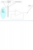
Now more specific question I am designing a kind of capacitive antenna (see attached jpeg). It is trying to sense voltage on a remote body by doing capacitive coupling of a metal plate with it. When voltage varies on body it causes changes in metal antenna nearby. I would like to buffer this signal. Note that as antenna (metal plate) is picking up very weak signal and i understand that I would need buffer with very high input impedance. So I selected LMP2231 **broken link removed** op-amp that has typical bias current of 20fA.


I know that on body signal is 60Hz with 400mV peak to peak. But what i get at buffer output is about 2 volts or more peak-to-peak 60Hz wave . I suspect this is to do something related to bias current or too much bias current (leakage to input pin on board perhaps). Will anyone have any explanation what could be occurring in the buffer that is causing amplified signal.

Thanks & Regards,
Mandeep
 

Attachments

  • circuit.JPG
    circuit.JPG
    60.5 KB · Views: 928
First, the TYPICAL input bias current for the subject opamp is 20fA; the MAX input bias current is +_50pA, more than a factor of 1000 higher...

The 60hZ pick-up has nothing to do with the input impedance of the the amplifier, it is caused by the parasitic capacitance between the nearest AC power line and your "Plate". The only way to make measurements of "charge" induced in your plate is in a Faraday Cage (shielded room). You cannot have any AC powered instrumentation inside the cage; everything has to run on DC, usually provided by batteries. At least the test structure shown in your diagram must be totally enclosed in a metal enclosure; every wire penetrating the enclosure must be routed through a LPF coaxial feed-through.

Another technique, if you can control the frequency of what is coupled to the "plate" (such as if you are building a capacitive sensor, which has both a charge "emitter" as well as a charge "detector") is to use a "lock-in" amplifier at a frequency removed from 60hZ and its harmonics. If you are working at DC, shielding the only technique that will work. Possibly a 60-Hz notch filter between the output of the opamp and where you are recording the data might help, but if the 60Hz contamination is so bad as to drive your amp rail-to-rail, then clipping happens and the systems become non-linear, so you cannot undo it by filtering.

Ref to your circuit. You cannot just use a "floating" input to the opamp. The source of the bias current has to come from somewhere, so you need an Ohmic path to a voltage halfway between Vdd and Vss to bias the input. How do you make a resistor which is high enough for your needs, but low enough to supply the required bias current?

Google "charge amplifier"
 
Last edited:
Thanks Mike for your reply.
First of all i apologize for goofing up part number. I am infact using LMP7721 **broken link removed** . This has max input bias current of only 20fA and typical of 3fA.

Let me clarify something more about my circuit:
1. I am infact interested in getting 60Hz. It is not noise for me it is the signal i am interested in.
2. My Circuit is battery powered by 3.7V battery.
3. Currently I do not have faraday-cage or shield around it. I am going to try it.


How do you make a resistor which is high enough for your needs, but low enough to supply the required bias current?
>> I don't think we can get resistor value that high. Even if we can get thermal noise (Johnson noise) in resistor will screw things up.

TI has a solution that is to connect JFET in reverse and take advantage of JFETs low gate leakage. Check http://focus.ti.com/lit/an/sboa058/sboa058.pdf. TI recommends Siliconix’s 2N4117A JFET for high input impedance applications.

My problem is 60fA is too high for me. Also it turns out that even etched PCB itself can not provide enough resistance between supply pins and input pin. Leakage can easily go upto 3fA and destroy amplifier's operation.

So now i am building circuit in air basically op-amp is in mid air and i am soldering respective pins directly to its pins.


But aside from my circuit, i have a fundamental question:
"Why op-amp need input bias current? Is input bias current is just a leakage from input port of op-amp IC to ground pin inside IC or Is it fundamentally a requirement of circuit inside IC?"

If someone can shed light on it, it will greatly help me increase my knowledge.

Thanks & Regards
 
But aside from my circuit, i have a fundamental question:
"Why op-amp need input bias current? Is input bias current is just a leakage from input port of op-amp IC to ground pin inside IC or Is it fundamentally a requirement of circuit inside IC?"

If someone can shed light on it, it will greatly help me increase my knowledge.
That current is just leakage, but it still has to have a path to ground. Otherwise the voltage on the pin will float to either the positive or negative rail and the op amp will saturate.

You can make a high value resistor by connecting a number of 10MΩ resistors in series.

To isolate the input, you can surround the input pin and traces with a ground plane or a trace going to ground. Thus all leakage paths would only be to ground, not the supply pins.
 
Op amps need bias current because the bjt emitter coupled diff pair at the input needs base currents in order to forward bias the b-e junctions into the active region. If the diff pair is well balanced the 2 bias currents are nearly equal and almost completely cancel if a bias resistor is used. The bias resistor should be placed in the positive input side and equal to the Thevenin equivalent resistance at the negative input terminal.

If this is done right, then the output error due to bias current is the feedback resistance, Rfb multiplied by the offset current Iofst, instead of Rfb*Ibias. For modern bipolar op amps, Iofst is less than Ibias.

Does this help?
 
Last edited:
Status
Not open for further replies.

Latest threads

New Articles From Microcontroller Tips

Back
Top