Can someone verify the gain of this op amp circuit?
The frequencies I will be testing the circuit at are 1, 10, 100 and 500 Hz.
I would like to know the method and values of the theoretical gain.")
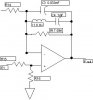
The circuit diagram is in the attachment.
Values are
R14 = 3570
R15 = 57600
R16 = 2320
R17 = 59000
C3 = 0.000000033 Farads
C4 = 0.000001 Farads
L1 = 6 Henries
The frequencies I will be testing the circuit at are 1, 10, 100 and 500 Hz.
I would like to know the method and values of the theoretical gain.
The circuit diagram is in the attachment.
Values are
R14 = 3570
R15 = 57600
R16 = 2320
R17 = 59000
C3 = 0.000000033 Farads
C4 = 0.000001 Farads
L1 = 6 Henries