Continue to Site

Welcome to our site!

Electro Tech is an online community (with over 170,000 members) who enjoy talking about and building electronic circuits, projects and gadgets. To participate you need to register. Registration is free. Click here to register now.

  • Welcome to our site! Electro Tech is an online community (with over 170,000 members) who enjoy talking about and building electronic circuits, projects and gadgets. To participate you need to register. Registration is free. Click here to register now.

Op-Amp Difference Amp- Variations

Status
Not open for further replies.

dknguyen

Well-Known Member
Most Helpful Member
I keep seeing this difference amplifier setup:
http://hyperphysics.phy-astr.gsu.edu/hbase/electronic/opampvar6.html

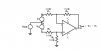
But never this one (image attached). It's basically a modified non-inverting amplifier where the reference is a voltage other than ground. Is there a reason for never seeing this circuit and always the first circuit? It seems to me both would work...why does it seem one is usually spoke off and the other one isn't? I need more of a "voltage de-biaser+amplifier" but I'm don't think that's any different from a difference amplifier where one input stays constant.


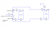
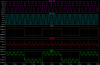
EDIT: It might be important for you to know that I am using a resistive dividier buffered with an op-amp to provide the bias voltage to the - terminal of the op amp. It's to detect motor Back EMF. The back EMF signal is biased at +V/2 (and the back EMF is always positive so the reading is always >(+V/2). WHat I want to do is remove this bias and then amplify it so I am only amplifying the back EMF and not the bias.
 

Attachments

  • Image1.gif
    Image1.gif
    16.8 KB · Views: 228
Last edited:
I think it's all there. I just cut out the part of the amplifier. , POwer temrina,s two inputs, and output. I can post the whole schematic if you want but then it's pretty big...The inverting input goes to a non-ground voltage (supposed to remove the bias in the signal at the non-inverting input), and the 9K on the non-inverting input is just for bias currents.

I think what I'm asking, is how is a non-inverting amplifier that has been biased any different from the difference amplifier circuit shown?
 
Last edited:
The diff amp amplifies only the difference between V1 and V2. The gain to any common mode signal (Vcm in the schematic below) is zero. You circuit does not have that feature, but probably doesn't need it.
Note that the input impedances to V1 and V2 are very different, so if V1 and V2 have significant source impedances, this circuit is not appropriate. The three op amp instrumentation amp configuration is better in that case.
 

Attachments

  • diffamp.PNG
    diffamp.PNG
    4.6 KB · Views: 187
I get the gain of my circuit to be G(V1-V2). Doesn't that get rid of any common mode signals anyways? THat equation is the same for the difference amplifier too (exept that G is calculated differently). THat's what I'm confused about, they both seem to do the same thing to me...

Or is that the reason you pointed out? THe input impedances for the + and - terminals are different? 9K = 10K||50K, Wouldn't that correct it?

(V2 is a my DC bias to be removed and not ground like a regular non-inverting amp).
 
Last edited:
dknguyen said:
I get the gain of my circuit to be G(V1-V2). Doesn't that get rid of any common mode signals anyways? THat equation is the same for the difference amplifier too (exept that G is calculated differently). THat's what I'm confused about, they both seem to do the same thing to me...

Or is that the reason you pointed out? THe input impedances for the + and - terminals are different? 9K = 10K||50K, Wouldn't that correct it?

(V2 is a my DC bias to be removed and not ground like a regular non-inverting amp).
To calculate common mode gain in your circuit, just short the two inputs together, connect them to a common mode source, and calculate the gain by superposition. The noninverting gain is 10, and the inverting gain is -9. Therefore the common mode gain is one. Any noise that is common to your signal and your voltage reference will be passed to the output unattenuated. This may not be a problem, because you probably don't have any common-mode noise.
To do the diff amp calculation, do the same thing with the sources. Be sure you look at the schematic I posted, because the turkey that created the web page you referenced used different designators for his 3 schematics.
The inverting gain is simply -R3/R1. The noninverting gain is
R4/(R2+R4)*(R1+R3)/R1. The overall common-mode gain is then
AV(cm) = R4/(R2+R4)*(R1+R3)/R1 - R3/R1
If R2=R1, and R4=R3, then
AV(cm) = R3/(R1+R3)*(R1+R3)/R1 - R3/R1=0
 
Yes, you did. I'm having trouble understanding why a signal and it's reference with common mode noise is any different from a differential input, since isn't the reference changing the same way the signal is due to the common mode noise to cancel it out? Except...oh wait, the signal isn't being referred to ground rather than the reference, right?
 
Last edited:
dknguyen said:
Yes, you did. I'm having trouble understanding why a signal and it's reference with common mode noise is any different from a differential input, since isn't the reference changing the same way the signal is due to the common mode noise to cancel it out? Except...oh wait, the signal isn't being referred to ground rather than the reference, right?
Now you've lost me. A perfect differential amplifier amplifies only the difference between the two inputs. It is completely immune to any signal that is common to the two inputs.
 
What I mean is, I'm having trouble seeing how non-differential, single ended difference amplifier won't get rid if common mode noise (CMN) if the reference and the signal both have the common mode noise. Won't they cancel each other out during subtraction?

(Sig+CMN)-(Ref+CMN) = Sig - REF?
 
dknguyen said:
What I mean is, I'm having trouble seeing how non-differential, single ended difference amplifier won't get rid if common mode noise (CMN) if the reference and the signal both have the common mode noise. Won't they cancel each other out during subtraction?

(Sig+CMN)-(Ref+CMN) = Sig - REF?
You're ignoring the fact that the gain to the two inputs on the circuit you posted are different. As I said in a previous post, the inverting gain is
Ginv=-90k/10k=-9
while the noninverting gain is
Gnoninv=1+(90k/10k)=+10.
To get the common mode gain, just add these together.
Gcm=-9+10=+1

EDIT: Correcting your equation,
10*(Sig+CMN)-9*(Ref+CMN) = 10*Sig - 9*REF+CMN
 
Last edited:
Maybe a visual aid will help convince you even more... :D
 

Attachments

  • diff amp.PNG
    diff amp.PNG
    10.9 KB · Views: 164
  • diff amp waves.PNG
    diff amp waves.PNG
    39.7 KB · Views: 146
One note on a differential amplifer where common mode rejection is one of the primary goals: the gain of either input with the other input grounded must be exactly the same, and as Ron indicates, the amp will then only amplify the difference between the two signals. In practice, often one of the feedback resistances is made a little smaller by a value of R and a small-value pot with a value of 2R is put in series with it. Then with a common mode signal (same signal fed to both inputs), you adjust the pot for as close to zero signal at the output as you can get.

Dean
 
Status
Not open for further replies.

Latest threads

Back
Top