Continue to Site

Welcome to our site!

Electro Tech is an online community (with over 170,000 members) who enjoy talking about and building electronic circuits, projects and gadgets. To participate you need to register. Registration is free. Click here to register now.

  • Welcome to our site! Electro Tech is an online community (with over 170,000 members) who enjoy talking about and building electronic circuits, projects and gadgets. To participate you need to register. Registration is free. Click here to register now.

ON/OFF Using Mosfets

Status
Not open for further replies.

momo1

New Member
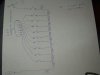
I have knowledge of electronics but not much into circuit building. I need some help to build a mosfet driver. Need to drive 10 mosfets at the same time for on/off function, basically to replace a few single pole switches. Looking for a single driver to drive them all together for simplicity. The mosfets will be killing the power to the balancing leads of a lithium battery pack installed inside an enclosure. Wanted to use the irfr2407 n channel rated at 75volt and 42amps. The max1614 driver can be controlled using a
small momentary button. If i can use that function to control all ten mosfets
then i can cut the power to the output leads on the battery pack and balancing leads. Lithium batteries when wired in series are charged individually
balancing each of the cell voltages in the pack. I have the battery pack installed inside a box. At the moment the wires to the motor controller and balancing charge leads are always on. Wiring them to mosfet transistors i can
turn them all off.
The max1614 probably cannot controll all of them with only a few ma output
current. What do you guys think?

https://pdf1.alldatasheet.com/datasheet- ... R2407.html

https://pdf1.alldatasheet.com/datashe...M/MAX1614.html
 
Last edited:
Can you give us a diagram of how the toggle switches are now connected to the batteries?
 
momo1 said:
The max1614 probably cannot controll all of them with only a few ma output current

Where did you get that impression?

The MAX1614 is a high side driver for N-Ch MOSFET. The datasheet indicates that it can output a max. of only 60uA(and typical 30~40uA) at a voltage higher than its supply voltage, via an internal charge pump, to drive ONE MOSFET gate to turn the MOSFET ON.

Typical example in the datasheet also mentioned gate capacitance of 800pF. The MOSFET you want to drive already has 2400pF gate capacitance each and you want to drive ten of them?

It is possible but it will take very long to do its job.
 
hello guys,

eblc1388, that was just a quick impression. Taking along time to do it's job is no good. What if i split them and use two 1614's?. Yes i want to drive ten of them.
I'm a little confused about the pf in the mosfets and the drivers.

k7elp60, I have attached a drawing of the switches.
 

Attachments

  • P1010371.JPG
    P1010371.JPG
    412.2 KB · Views: 227
momo1 said:
hello guys,

eblc1388, that was just a quick impression. Taking along time to do it's job is no good. What if i split them and use two 1614's?. Yes i want to drive ten of them.
I'm a little confused about the pf in the mosfets and the drivers.

k7elp60, I have attached a drawing of the switches.

Can you post a circuit of where the balancing leads connnect to, in other words a full schematic would be helpful.
 
momo1 said:
What if i split them and use two 1614's?. Yes i want to drive ten of them. I'm a little confused about the pf in the mosfets and the drivers.

Are all these MOSFETs source voltage the same? i.e. they all connected to the same point in the circuit?

If not, I don't see how you can drive ten of them using one or two drivers.
 
Ok, this is how they are balance charged. The port labeled to estation charger temp sensor. This will monitor each cell voltage on the charger and displayed
on the chargers screen.
 

Attachments

  • PB6-dual.gif
    PB6-dual.gif
    44.4 KB · Views: 201
  • battery charger.JPG
    battery charger.JPG
    421.5 KB · Views: 306
momo1 said:
Ok, this is how they are balance charged. The port labeled to estation charger temp sensor. This will monitor each cell voltage on the charger and displayed
on the chargers screen.
Based on the availible information I would use a pair of 4PDT relays powered from the charger and then use one switch to control the relays.
 
The relays would be very simple but i was hoping for something using mosfets
so i can learn at the same time. Each cell has 3.6volts for a total of 36volts.

If i can at least control the output 36v on and off then i can save battery
power by not using a relay having to feed a coil. The battery drain on the
load can go up as high as 40amps. I found this mosfet that should work
great.

https://pdf1.alldatasheet.com/datasheet-pdf/view/131924/IRF/IRFB4110PBF.html
 
I assume the FETs don't need to carry the load, only the charging current. What is the charging current?
 
Hi, The charging current through the balancing connector is very minimal less
than 1amp. The charging current through the load connector is 10amps to fully charge in 20 minutes.

Once the battery is fully charged through the 36v (load) leads the balancer begins to charge each cell independently until they all reach the same voltage
using the balance connector.
 
Last edited:
If using relays, the only time the coils would draw current is when the batterys are be charged. If you use 12V coil relays with a series resistor the current for each coil would be about 100mA.

If you still want to use power mosfet's I'll try to help you with your circuits.
I am a little confused as you say there are 10 batteries of 3.6 volts each, yet in the posting showing the equilizer there are 4 batteries in series of 3.6 or a total of 14.4. Each battery pack is in parallel with the charging voltage. So the charging voltage is around 14.4 volts then, or do I have it all wrong?
 
Hi k7elp60, I do understand the situation using relays. The power to the
coils could come from the charger or an external source, installing these relays before the balancing connector. But for the negative and positive output leads i'd rather use a mosfet.

I see where your confused, sorry for that. The picture was taken from their
website. One balancer can balance anywhere from 2-6 cells. My hand
written drawing shows exactly how my battery pack is wired. 10 cells
of 3.6volts each for a total of 36volts.
thanks
 

Attachments

  • P1010371.JPG
    P1010371.JPG
    412.2 KB · Views: 171
If you really want to use a MOSFET then you'll need an isolated control circuit for all MOSFET switches not connected to circuit ground. One way is to use a small transformer with a diode rectifier output on the secondary connected between the gate and source of the MOSFET. Applying an AC voltage to the transformer primary will generate a rectified voltage at the gate and turn on the MOSFET. When the AC is removed the transistor will turn off. Since the MOSFET requires only leakage current to drive the gate, the transformer can be very small. Typically the transformer would have to deliver about 11V peak to turn on the MOSFET which usually require 10VDC for full turn-on.

The control circuit would consist of a transformer, a diode to the MOSFET gate, a gate-source capacitor to filter the AC, and a gate-source resistor to sink the gate leakage current and turn off the transistor when the input AC is removed. The circuit is not fast but your application does not require speed.

This can be expanded if you want to control all the lines with MOSFETS. You could use separate transformers and rectifiers for each MOSFET, or one transformer with multiple isolated rectifier outputs for all transistors that turn on and off together.
 
I am not an expert on Power Mosfets, but I have been able to turn them on if the gate voltage is about 10 volts higher than the source voltage and a small resistor is put in series with the gate terminal to overcome the gate to source capacitance. Most mosfets also have a maximum gate to source voltage. The ones I looked at this was 20 volts.
Here is a possible solution. I used P channel in the top three switches because if N channel were used then a voltage pump would be required to boost the gate drive voltage. Individual mosfet drivers could be used for N channel mosfets for the top three as another solution.
See attached diagram
 

Attachments

  • mosfet driver.jpg
    mosfet driver.jpg
    69.4 KB · Views: 188
k7elp60's resistor approach looks good, simple but effective.
 
k7elp60, I understand the resistor approach on the gate to source to overcome the capacitance which will allow the mosfet
to turn off. When you added three p channel fets that is where i am confused, especially when i would need individual mosfet drivers to boost the gate drive voltage. I think i will get a few and play around with them.
 
momo1 said:
k7elp60, I understand the resistor approach on the gate to source to overcome the capacitance which will allow the mosfet
to turn off. When you added three p channel fets that is where i am confused, especially when i would need individual mosfet drivers to boost the gate drive voltage. I think i will get a few and play around with them.
The 180 ohm resistor from the gate to the voltage source helps compensate for the gate to source capacitance. The 1M resistor from the gate to source is there for two purposes. 1 to prevent false triggering by noise and to help with the turn off the mosfet when the gate voltage is removed.
I chose P channel mosfets so I didn't have to use individual drivers because the gate has to be about 10V higher than the source voltage. By using P channel mosfets and connecting the source to the supply and the drain to the load it overcomes that problem, even thou it is a postive voltage on the gate is at least 10V more negative than the source.
If you use N channel mosfets for the top 3 switches you have two approaches. 1. use individual drivers or 2. use a voltage pump to boost the gate voltage to about 46V.
 
How fast do you want this to switch?

Ten of those MOSFETs will have a gate capacitance of 24nF, assuming the driver puts out just 30:mu:A and the MOSFET turns fully on, I calculate the turn on time to be 8ms. This is no good if you're building an SMPS or a PWM motor speed controller but if it's just a simple relay type application, then it's more than fast enough.
 
Status
Not open for further replies.

Latest threads

New Articles From Microcontroller Tips

Back
Top