Continue to Site

Welcome to our site!

Electro Tech is an online community (with over 170,000 members) who enjoy talking about and building electronic circuits, projects and gadgets. To participate you need to register. Registration is free. Click here to register now.

  • Welcome to our site! Electro Tech is an online community (with over 170,000 members) who enjoy talking about and building electronic circuits, projects and gadgets. To participate you need to register. Registration is free. Click here to register now.

old computer power suply

Status
Not open for further replies.

bogdanfirst

New Member
today, someone gave me a computer suply, he told me it is not functioning. so i tooke it for components.
ill start with what i want. i dont want to repaire it, i just want to know it is posible to use the components to build another switching suply, from 12-18Vdc to adjustable 3-12V. or any other switching suply for input low voltage d.c. and output low voltage d.c. too.
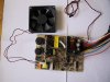
the thing is that i opened it and didnt find anything to be wrong in it, anything burned, exept for a resistor wich was connected between +12V and the fan circuit(the fan has a turation control circuit with a sensor attached on a heatsik, wich you can see in the picture it is a little pcb with 2 wires-red and black-coming from the main pcb and the fan is connected to this pcb too.). the resistor seems to be the only thing to be non functioning.
there are 2 IC's DBL339 and DBL494. i didnt search for a datasheet for them, but i will. probably these ics are for controlling the sulply. there is a big transistor, LT57(SBL1640PT) and 2 other smaller ones, C3039(M5J4), plus more other low power transistors. i also see three transformers and 5 inductors. there are 2 cpacitors, 220uF/200V wich dont appear to be broken.
well in conclusion i want to ask if anyone has any circuits for the components i mentioned, or any ideea of what to do with it before i break it apart in components.
 

Attachments

  • 141-4113_IMG.JPG
    141-4113_IMG.JPG
    69 KB · Views: 7,085
Hi,
the DBL494 equal to TL494, DBL339 = LM339. As i see it`s a simple 200W PSU. First try repair it. When can`t started, connect min.1A load to 5V out and and switch on. If the bridge rectifier output is about 310V and no output, maybe you can hear a small scrape from transformer. It is good, the two transistors in half-bridge try startet, but can`t,because output have a shortcircuit. (often one fast recovery diode in negative rectifier)
If working fine, you can remove all components of LM339 it`s an overvoltage protection,no more need. (it compare +5v to -12V and +12V to -5V and give PG out.)
TL494 pin1 the voltage feedback.Here is (often two) resistors to GND.When this resistor decreased, output voltage increased.
I don`t think possible the output tuning up to 18V, but ten years ago i`ve modified one for accu charging, work fine with 14.4V 15A.
 
well i decide to tare it apart and i did aprt of it. as i said , i am not intersted in repairing it, but i want to do something with the components.
thanks for the equivalece. ill see what i will do to it.
 
anybody got any switching suplies that i can make with some components of the suply, especialy with the ICs and coils.
what i mean, i wanna build any thype of switching PSU, no matter what power or voltage.
just for fun and learning.
hope to hear from you soon.
 
With these parts rebuild a power supply results same as original.
What You need for output? When You repair it i can say the tuning method from 8..15V and 3...7V.
 
no, what i mean, i dont need such a high power, and not necesarry to convert from mains a.c. to a low voltage, just a switching psu. i just wanna see how one works, i havent build one before.
 
Basically the maximum output voltage you can achieve is going to be determined by the winding on the transformer that supplies the 12v output.......altering the feedback resistors to pin 1 on the TL494 will have a limited effect because : the switching time of the oscillator is fixed( usually around 50khz) and the range of the pwm.......the maximum on time of the transistors determines how much power is put into the transformer...the transformer is wound to give a 12 v output any way so you wouldnt gain anything by modifying the power supply if you were looking to obtain more than about 14v output........


HTH Chip
 
no, actualy what i would like to build is a 5V suply but not form mains, but from a voltage form 6 to 14 somewere in that arange,with 0.5A max output current, or a converter from a 6V lead acid batt to 12 V, 1A max current.
maybe you know some schematics.
actually i only need the coils from this suply, baceause i cant find any to buy here, the rest components from the suply i can find to buy, so i was looking for a schematic to use the coils.
 
modifying old computer power supplies

Hey guys...need some help. Has anyone ever modified a PC PSU to output higher current? Or connected multiple PSUs in parallel to get higher current? I'm needing a power supply that can deliver +5V @ 100 Amps or more. Its for an electroplating project. The current would need to be variable output. A good example of what I need is like the rack mount test equipment PS that HP/Agilent makes.
 
the powersupply i have has a clearly seperated High voltage part and a low voltage part, in between are two transformers, one large CWT-01 HM9706 and a smaller CWT-02 HM9706.

The larger has 4 high voltage leads and 5 low voltage which i can`t seem to measure the voltage from :S

The smaller had 5 high voltage leads and 3 low voltage

There is one chip (DBL 494).
And a lot of diodes, resistors, transistors, caps and a coil in the low voltage part with 10 leads.
 
Maddog_rvo said:
Does anybody have an idea to mod such a powersupply for 14V input (in the car)

Basically a total rebuild, you would need to rewind the transformer primary and redesign the complete primary side of the PSU.

If you search for car MP3 players there are various designs for computers in cars, usually building a PSU from scratch.
 
Nigel Goodwin said:
Maddog_rvo said:
Does anybody have an idea to mod such a powersupply for 14V input (in the car)

Basically a total rebuild, you would need to rewind the transformer primary and redesign the complete primary side of the PSU.

If you search for car MP3 players there are various designs for computers in cars, usually building a PSU from scratch.

Hmm i hoped to find something usefull on the secondary side of the transformer, like a 12V or 20V lead out... that would have been a nice starting point :D only can`t find anything like that, i hoped i didn`t need to build one from scratch, i did fine one to build from scratch

**broken link removed**

only i don`t get the parts, i`m from holland and i don`t think it`s wise to order all the things in the US, if i do that i better buy a premade powersupply in a store. I don`t have much money so i don`t want to spend too much
 
bogdanfirst,

Before design a SMPS, you need to decide basically 4 aspects:
1) Output Voltage
2) Input Voltage
3) Output Current
4) Toplogies Used

Otherwise, it seems that it is so good to say anything about using which choke, any voltages.... :)

Candy :wink:
 
Status
Not open for further replies.

Latest threads

New Articles From Microcontroller Tips

Back
Top