Continue to Site

Welcome to our site!

Electro Tech is an online community (with over 170,000 members) who enjoy talking about and building electronic circuits, projects and gadgets. To participate you need to register. Registration is free. Click here to register now.

  • Welcome to our site! Electro Tech is an online community (with over 170,000 members) who enjoy talking about and building electronic circuits, projects and gadgets. To participate you need to register. Registration is free. Click here to register now.

Ok for filament bulbs to burn but not for LED lights

Status
Not open for further replies.

kellogs

Member
Hey,

As I was researching into load dump protection I have come across this document from TI which says:

The governing specification for tail light electronics is that they be able to
withstand transients of +100 V and -300 V. This is a foreboding challenge for IC based electronics such as
LED tail light regulators.

Now, I don't suppose there is anything built-in for the regular incandescent lamps to protect them against such events, and at that kind of overvoltage it won't take more than some 10 microseconds for them to be destroyed. Or, perhaps i am missing something. Comments ?
 
yes you are correct, filament aging depends on temperature which normally has a > 100 ms response time
 
Last edited:
The large voltage spikes of +100V or -300V will be for a very short time, and will also be a relatively high impedance so a filament light would reduce the voltage a lot.

The negative pulse would come from an inductive load in parallel with the device, when the supply is disconnected. The +ve pulse would come from inductance in series with the device when the device, or something in parallel with the device, stops taking load.

A typical inductance wouldn't be large enough to maintain the current for more than a few microseconds so the heating wouldn't last long enough to significantly heat a filament.

The voltage spikes are a much larger problem for electronics, which can be much higher impedance and would be damaged by very short pulses if the voltage is high enough.
 
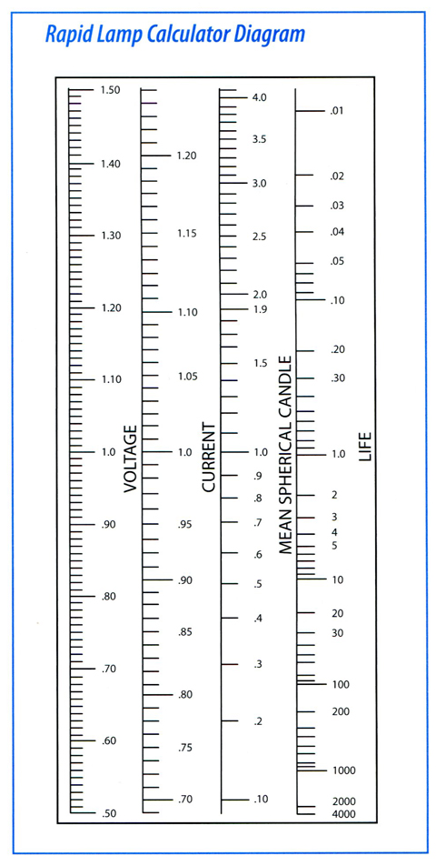
Thanks for the answers. Is this formula correct ?

file.php


Halogen_Lamps-TechDisc-ILT_Sources_Catalog_pg08-2.jpg


If yes, for an average 12V @ 1000 hours bulb it would take a mere 3.85 microseconds to burn out @ 100V
 
I don't think that the formula would be maintained at such an extreme voltage.

For one thing, the filament wouldn't have time to get to an even temperature.

The more important feature here is that the inductances that produce the pulses don't have enough energy to heat a filament significantly. One of the standard methods of protecting electronics from pulses like those is to add a transient voltage suppressor (TVS) in parallel with the device. That works because the TVS can divert the current and keep the voltage lower. A filament lamp will keep the voltage down just as effectively.
 
That's good news then. At least for the faster transients. Any comments for the much slower load dump - up to 400 ms, down to 0.5 ohm Ri, up to 100V peak ?

A filament lamp will keep the voltage down just as effectively.

I would assume only when placed in series with the circuit to protect and only when it's resistance is considerably larger than that of the circuit to protect. Could you elaborate on this please ?
 
That's good news then. At least for the faster transients. Any comments for the much slower load dump - up to 400 ms, down to 0.5 ohm Ri, up to 100V peak ?


I would assume only when placed in series with the circuit to protect and only when it's resistance is considerably larger than that of the circuit to protect. Could you elaborate on this please ?
The fast transients that produce more than 100 V come from the inductance of the wiring or of other loads. There isn't a lot of energy in those, so if there is a significant load like a filament light (or a TVS) in parallel, the peak voltage will be significantly reduced.

Load dump is a different thing entirely. When load dump occours, the energy comes from the engine, and a load such as a small filament bulb won't reduce the voltage much, so there is a risk that they will be blown by a load dump.
 
Where there is a high-impedance supply, extra elements in parallel will cause the voltage to be reduced. The high-voltage pulses come from comparatively high impedance sources, so it doesn't take a lot of current to reduce the voltage.

The pulse specification of +100 V /-300 V is with no load. Any load, whether it's a TVS or a lamp will reduce the voltage.

In the example of a negative pulse, that can come from a relay coil when the supply is removed. The relay coil has significant inductance and so the current can't change instantly. The -300V is the worst case when there is nowhere for the current to go except to charge up some stray capacitances.

It's quite common to add a resistor in parallel with the relay coil to reduce the voltage. Here is an example data sheet:- https://www.farnell.com/datasheets/1934206.pdf

On the standard 12 V relay, the coil resistance is 90 Ω, and there is an option of a resistor which is usually 560 Ω. If a relay coil like that is suddenly disconnected, the current in the coil will be 12/90 = 133 mA. That current will flow in the 560 Ω resistor, giving a voltage of around 75 V. When that happens the resistor has limited the voltage rise to 75 V. Without the resistor, the voltage rise would have been much larger. With a known limit of 75 V, it's quite easy to specify a suitable transistor to switch the coil current.

It is that type of voltage surge that the standards are there to protect against. A 1.2 W filament light will have a resistance of around 120 Ω, so if one of those were in parallel with the relay, it would limit the voltage surge to around 16 V, which isn't significant. Larger lamps would reduce the surge voltage further.

Resistors like that are often used in preference to diodes, because they can't be connected the wrong way round and because the current in the relay coil falls much faster with a resistor than with a diode. That means the that the contacts open faster, reducing arcing.
 
pulse specification of +100 V /-300 V
I see this little in cars but trucks, busses and trains have a real problem. These spikes are short in time and the wiring length and frame length causes inductance. It is common to have a wire with 300V on one end and 12V on the other. (for 10uS)
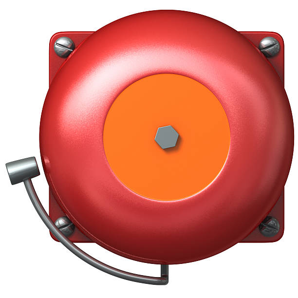
We had a batch of school buses where someone added a bell at the back of the bus. The bell had a coil to drive a hammer, a switch that cut power to the coil when the hammer was in motion. There was a large current flowing in the frame of the bus with very sharp edges. The radio and computers reset when the bus was backing up.
fire-bell-picture-id121227092
 
That means the that the contacts open faster,

I did not know about that, thanks!

The datasheet above says:

A low resistive suppression device in parallel to the relay coil increases the release time

Something escapes my logic on the two quotations

Back to original question - vehicle lights are connected in series with a relay NO circuit between 12V and GND. I believe there are no parallel light bulbs / TVS diodes on this circuit branch. Or maybe i misundestand and the light bulb actually does act as a parallel load to other inductors causing the spikes ? TI says:

The governing specification for tail light electronics is that they be able to withstand transients of +100 V and -300 V. This is a foreboding challenge for IC based electronics such as LED tail light regulators.

Do they imply that the LED & surrounding electronics have to be protected, whereas a regular bulbs not ? I have understood that high impedance pulses in the microseconds range won't cause any harm to them, but what about a load dump event ?
 
A relay contacts will open faster if the coil current reduces faster. The slowest practical reduction happens when there is a diode in parallel with the coil. A resistance in parallel will be faster than that, and the fastest will be if there is nothing in parallel, but that can lead to a very large voltage spike.
 
Electronics in cars will usually be specified to survive a standard set of pulses. It doesn't matter how the particular bit of electronics is connected. I agree that a NO relay powering a single lamp is unlikely to cause problems.

However, if there are several circuits all powered from one high-power fuse, and something makes that fuse blow when the lamp is turned on, there could be a big voltage surge for the lamp. If the car manufacturer designs every electronic module to withstand the worst case, then nothing worse will happen.

The electronics feeding an LED may well be more sensitive to a high voltage spike than a filament light. The ability to resist the surges is why some devices are made in a very simple but inefficient circuit. I recently examined a VW indicator assembly. It used one 3 V LED, fed by simple dropper resistors. There was a diode for reverse polarity protection. A switch-mode supply would be more efficient, but would cost more to make, would be heavier, and would be more difficult to protect against spikes.

A load-dump even could well damage a small filament lamp. Some alternators use zener diodes as the rectifiers to limit the voltage during load-dump to 32 V or so.
 
The electronics feeding an LED may well be more sensitive to a high voltage spike than a filament light. The ability to resist the surges is why some devices are made in a very simple but inefficient circuit. I recently examined a VW indicator assembly. It used one 3 V LED, fed by simple dropper resistors. There was a diode for reverse polarity protection. A switch-mode supply would be more efficient, but would cost more to make, would be heavier, and would be more difficult to protect against spikes.

I've repaired various LED assembly from cars, third brake lights, indicators, etc. - and all were simple chains of LED's and resistors, they may have had a reverse protection diode, I can't recall, but certainly no switch-mode stuff.

Efficiency isn't a concern in a car, for such light loads at least, but reliability is - and a resistor is more reliable than a switch-mode PSU :D
 
Some trailer lights and aftermarket LED lights designed to replace incandescent bulbs have switch-mode current regulators.

The advantages are that there is less heat to dissipate and that they can work on 12 or 24 V without modification. They are probably less worried about EMC problems than a car manufacturer would be.

However, I agree that efficiency isn't usually important. Many cars are still made with incandescent lights. Also on some 12 / 24 V trailer lights there are two strings of LEDs plus resistors that are in parallel for 12 V and in series for 24 V.

I've also seen linear current regulators on car LED lighting. It avoids having switching and EMC problems, but eliminates the brightness variation with voltage changes.
 
Status
Not open for further replies.

New Articles From Microcontroller Tips

Back
Top