Continue to Site

Welcome to our site!

Electro Tech is an online community (with over 170,000 members) who enjoy talking about and building electronic circuits, projects and gadgets. To participate you need to register. Registration is free. Click here to register now.

  • Welcome to our site! Electro Tech is an online community (with over 170,000 members) who enjoy talking about and building electronic circuits, projects and gadgets. To participate you need to register. Registration is free. Click here to register now.

Odd device inside central locking motor.

Status
Not open for further replies.

Diver300

Well-Known Member
Most Helpful Member
The central locking one my daughter's 2004 Nissan Micra was only working sometimes, so I had a look at it. I don't think that the lock is supposed to be repaired, but they are probably quite expensive, and I would have to wait until Monday or later to get one, so I opened it up.

There are two motors, and the larger one had quite a high resistance, around 20 Ω, and it wasn't working. When I connected a power supply, the current was only 200 mA or so, and it reduced when left connected for a few seconds.

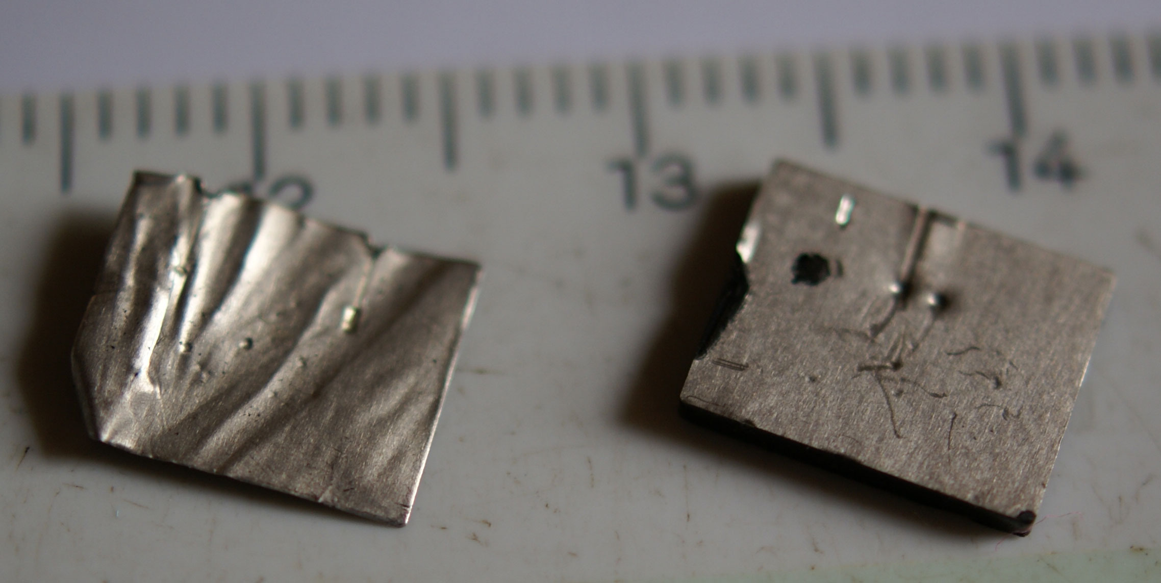
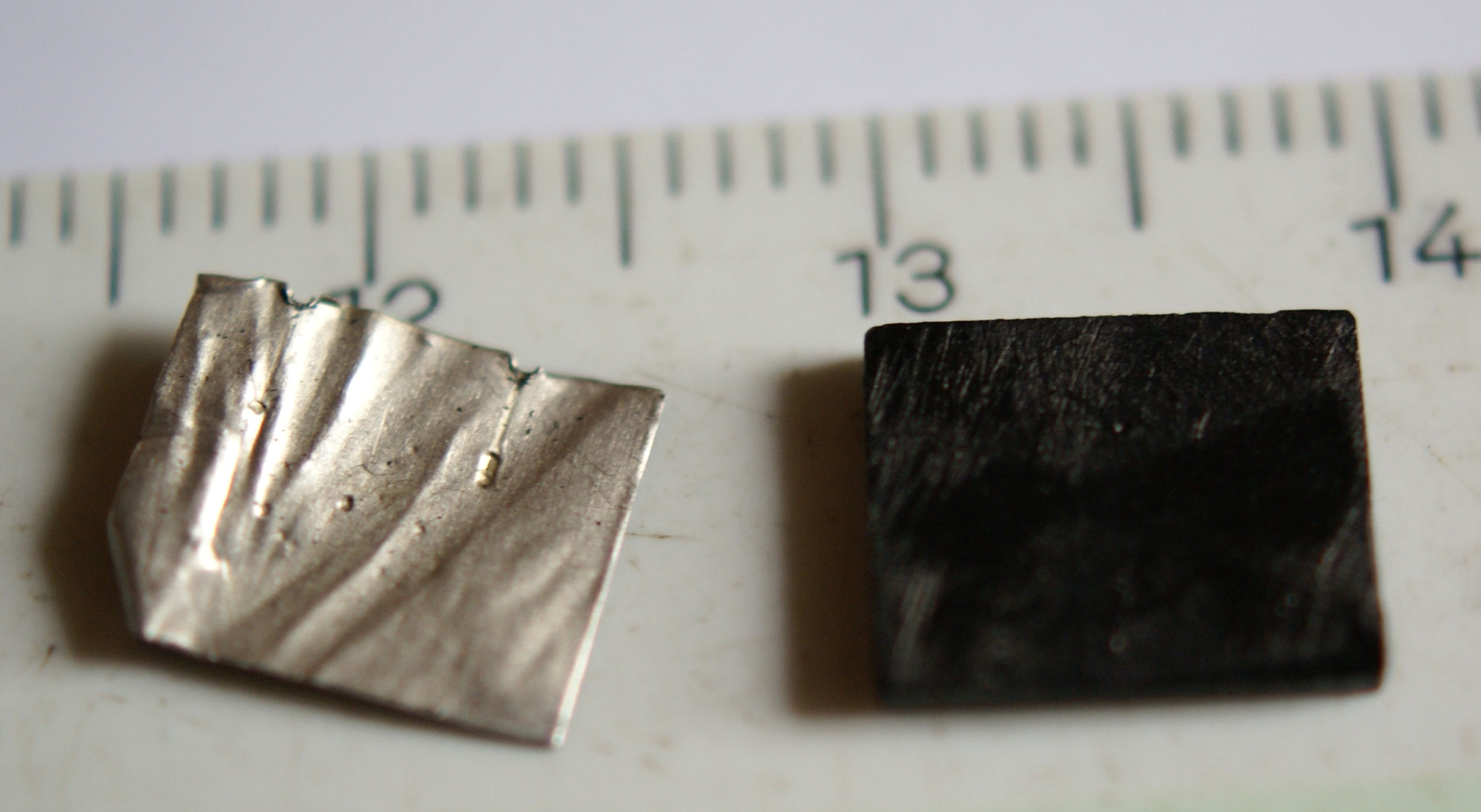
Inside the motor there was a component in series that I can't recognise that provided most of the resistance. The motor itself is around 2 Ω. The component is around 10 x 8 mm, around 2mm thick. It appears to be graphite or similar, with a foil electrode on each 8 x 10 mm face. The electrical connection is made to the foil electrodes.

Has anyone got any idea what this component is?
 
It could be an NTC ICL inrush current limiter.
 
Window motors have a form of 'electronic CB' so you can stall them up or down without damage, I have never looked into one, but this could be something similar?
Max.
 
Thanks for those suggestions.
The shape of the device is very different from anything that I have seen before, but I guess that there are so many cars made that very specialist components are worth using. The central locking motors don't have conventional terminals. The locking assembly connector pins are made in one piece with pins which engage with the motors. The construction of that is similar to car tail lights, where a single sheet of metal is pressed into bulb contacts and connector pins.
The pictures show the foil electrode that I peeled off one side of the device, and the main part. I tried filling it down to make it thinner and lower resistance, but I couldn't make a good contact so I gave up.
thing1.jpg

thing2.jpg
 
It is common for parts to be made in custom high volume , low cost , exclusive for automotive and this looks quite unfamiliar.

But most common motor locked rotor protection is a PTC device properly sized for holding current and thermal time constant to reach around 85'C or whatever the temperature that raises the resistance exponentially. Aging will rapidly raise the cold resistance which may be why this part is 10x the motor coil resistance instead of nearly equal to limit locked rotor current in half to 4x instead of 8x Iavg, then rise rapidly to >100x resistance.

From thus picture it seems the only attachment is the foil pressure contact to the metallic oxide material. I doubt but cant be certain it is not a ferric oxide choke, but you can test the material properties from both sides with foil contacts squeezed with finger pressure.

They probably used an ultrasonic welder for wire contact to foil.

If you need to replace it, consider sizing a PTC to match the coil Rs of 2 Ω or follow this guide. https://www.te.com/usa-en/videos/co...hoosing-the-right-polySwitch-pptc-device.html
 
Last edited:
Status
Not open for further replies.

Latest threads

New Articles From Microcontroller Tips

Back
Top