Continue to Site

Welcome to our site!

Electro Tech is an online community (with over 170,000 members) who enjoy talking about and building electronic circuits, projects and gadgets. To participate you need to register. Registration is free. Click here to register now.

  • Welcome to our site! Electro Tech is an online community (with over 170,000 members) who enjoy talking about and building electronic circuits, projects and gadgets. To participate you need to register. Registration is free. Click here to register now.

NPN Transistor High Side Mosfet Drive

Status
Not open for further replies.

jrudd

New Member
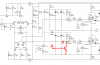
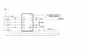
I've reduced my H-Bridge down to a single N-Channel Mosfet(IRF540) driving a small brushed DC motor for testing purposes. Drain is to +12vdc, source to motor,motor to gnd.
According to the scope, the bootstap circuit is providing a goodlooking 22vdc pwm (about 2k hz)to the gate. Should be fully on. My question is this, if I replace the motor with a 10ohm,10watt resistor, I can crank the pwm up to 100%(12vdc) and observe a steady 1.13amps while the fet doesn't even get warm. If I put the motor back in place of the resistor, I can only crank it up tp .50 amps and the fet gets too hot to touch. I'm assuming the inductance of the motor has something to do with that but I don't know how to deal with it.
One other question, how many amps should a properly driven , high side, not heatsinked fet deliver before getting to warm to touch(about 135F).
Thanks for any help.
 
Q: Why are you using a high-side fet instead of using an n-channel low side? Does the motor need to be grounded?

Also, do you have a freewheeling diode across the motor?
 
Last edited:
How much current? Taking the data sheet values: 65C per watt, 135F (57C) is 30-32C temp rise, so just under 1/2 watt. On resistance 44 milli ohms. P=(I^2)*R; or I=sqrt(P/R) or I=sqrt (0.5/0.044) = about 3.3 amps.

ymmv, if it's enclosed, or if the air is moving, or if it's warm or cold, etc.

If the MOSFET is switching (PWM) or not fully turned on, this will increase the dissipation.
 
Last edited:
22v Vgs is pretty unsafe for most MOSFET - 10v is a lot better.

did you have a diode on the motor?

As to power dissipation, for most to220 devices without a heatsink, 1w is a safe number. the irf540's datasheet has thermal resistance of 62c/w junction to ambient (with no heatsink). that means you have 120c to go before it reaches 150c junction temperature, assuming a 30degree ambient temperature. that means <2w of total power dissipation.
 
N-Channel

I'm using the N-Channel on the High Side because I want to be able to do a full bridge drive and I need to learn how to drive a High Side N-Channel properly.
I used a 1N4148 across the motor as the flyback diode.
The 22vdc to the gate is relative to GND, so thats 10vdc above the drive voltage of 12vdc which should be good. I've attached the circuit I am copying. I used it pretty much verbatim except I have a .1uf bootstrap cap vs the 10uf recommended.
As I mentioned previously, it looks like this circuit is working good on the pure resistive load(fet runs cool at 1.0amp to load), however, the fet heats up running the motor at only .50amp.
 

Attachments

  • bootstrap.pdf
    278.1 KB · Views: 1,558
a few things:

1) that 1n4148 is likely fried. something like a 1n4001 is more appropriate.

2) .1u for 2khz swithching may not be enough. you should go through the calculation to make sure that .1u works, as well as a 1n4148 works - if the charge-up current is too high, you should put a serial resistor with the 1n4148.
 
a couple observations about the driver:

1) the gate is being charged up through a 1k resistor: that's fairly large considering that the gate capacitance is likely over 3000p for irf540.

2) there is no way for the gate to be discharged.

so the combination means soft turn-on and soft turn-off of the mosfet -> large power dissipation.
 
Thanks for the help. I didn't realize how light duty that fast switching 1N4148 is.
I'm going to pick up some 1N4001 diodes at Radio Shack tonight as well as some larger caps for testing. I'm going to put a heat sink on that fet to hopefully allow it to drive the motor long enough at .50amp so I can get a look at the Drain with the scope to see how much soft on and soft off I am getting. I'll try to go through those equations again for sizing the bootstrap cap and diode.
Although I would think that if I had a lot of soft on and/or soft off, the fet would heat up while driving the resistor as well. I have a feeling that I'll see a difference using the 1N4001 diode across the motor.
The problem of ""How can the Gate discharge", I thought about putting a 10k pull down on it.

Thanks again.
 
The problem of ""How can the Gate discharge", I thought about putting a 10k pull down on it.

Thanks again.

I don't know but it may not work at high speed (then 2khz isn't too high), and you lose the driver voltage.

take a look at this schematic (from Philips). Q11/Q12 are there to bleed the gates. it should help you nail down component values.
 

Attachments

  • level shifter.PNG
    level shifter.PNG
    53.2 KB · Views: 7,451
your motor is an intermittent load with rapidly changing voltage to ground....the gate threshold needs to be more than seven volts above the load to conduct current with minimum loss...a photo coupler could insure a solid switch pulse to gate by isolating gate to source drive from ground and a pull up resistor would insure hard turn on....limit gate to source to 10 volts with zener or divider
 
Last edited:
Yes, I think poster Joe has something. Measure the voltage from source to gate (instead of ground to gate) both with the resistor load and with the motor load. You may find the voltages are not the same, that the FET is not being fully turned on and/or off, in the case of the motor load.
 
Last edited:
H-Bridge Running Fine

Sorry I haven't posted any results of my testing sooner. With the help of several folks on the forum I have been running the H-Bridge successfully using the transistor and bootstrap style high side drive and also using the
IR2110 driver. I discovered that the bootstrap diode I was using (1N4148)was too light and not allowing the gate drive voltage to get as high as it should.(i.e with the 12vdc, the gate drive should have been about 10vdc above that or 22vdc). I switched to the 1n4001. I also discovered that the bootstrap cap I was using (.1uf) was not large enough. I'm now using a 1uf bootstrap cap and am getting a solid 22vdc gatedrive voltage. The fets are not heatsinked yet but I can run them close to 3amps without getting too hot to touch(about 130F).
I also discovered that you can increase your gatedrive voltage easily by increasing the size of the bootstrap cap, however when I used a 10uf cap, I was getting around 32vdc gate drive voltage until something happened to the IR2110. The specs indicated that Max Allowed gate drive voltage would be your Battery or supply voltage plus 20vdc that put me running right at 12+20 or 32vdc which burned out the IR2110.
My next step is to add radio control capability and then create a double sided board with enough copper to support the 30amp fet capability. Would appreciate anybodys recommendation on a good system for making your own double sided boards.
Thanks, John
 
Put 18v zeners on the gate-source of the mosfets. They will drop any transients to the gate, which there always are spikes using a bootstrap cap.

Also put a 100pF ceramic cap between the drain and source of the mosfets. They will reduce the turn-on and turn-off ringing that occurs. Another source of failures.

Don't use any resistors between the drivers and the gates themselves. Mosfets do not need to be current limited at all, and it just slows down the switching speeds.
 
H-Bridge

Thanks for the advice. You are right, I am seeing a lot of ringing when looking at the drain or source to ground on the scope and was wondering what to do about it. I will add the ceramic caps to see if that will help. And yes, I do have resistors on the input to the gates which I will be removing.
Thanks again,
John
 
Sorry I haven't posted any results of my testing sooner. With the help of several folks on the forum I have been running the H-Bridge successfully using the transistor and bootstrap style high side drive and also using the
IR2110 driver. I discovered that the bootstrap diode I was using (1N4148)was too light and not allowing the gate drive voltage to get as high as it should.(i.e with the 12vdc, the gate drive should have been about 10vdc above that or 22vdc). I switched to the 1n4001. I also discovered that the bootstrap cap I was using (.1uf) was not large enough. I'm now using a 1uf bootstrap cap and am getting a solid 22vdc gatedrive voltage. The fets are not heatsinked yet but I can run them close to 3amps without getting too hot to touch(about 130F).
I also discovered that you can increase your gatedrive voltage easily by increasing the size of the bootstrap cap, however when I used a 10uf cap, I was getting around 32vdc gate drive voltage until something happened to the IR2110. The specs indicated that Max Allowed gate drive voltage would be your Battery or supply voltage plus 20vdc that put me running right at 12+20 or 32vdc which burned out the IR2110.
My next step is to add radio control capability and then create a double sided board with enough copper to support the 30amp fet capability. Would appreciate anybodys recommendation on a good system for making your own double sided boards.
Thanks, John
can you post your final schematic? I am trying similar thing....
 
Latest Schematic V3

I'm sure there will be changes. I want to add thermal shutdown(or slowdown) by sensing the temp of the high side fet heat sinks.
 

Attachments

  • Dual H-Bridge.pdf
    405.1 KB · Views: 957
You have 3.3k resistors in series with the gates of the Mosfets. Then the Mosfets turn on and tunn off very slowly due to their high gate capacitance. When they switch slowly then they get very hot.

The 3.3k resistors should be 10 ohms to 47 ohms to prevent the Mosfets from oscillating at a VHF or UHF frequency that will also cause them to get very hot.
 
What causes the oscillation? I have not run into this in any of my research and would like to understand it.

Could it be the turn-on/turn-off ringing of the drivers?
 
Last edited:
ir2110 testing???????

Can you please explain me how to test ir2110 IC...I don't understand what I get the results....here is what i have done....

To test ir2110, I just make this connection shown in the figure..

I have tested following cases...1. HIN=LIN= +5V, LO=0, Ho=15V
2. HIN=0, LIN=+5V, LO=0, HO=15V
3. VDD=HIN=LIN=5V, same results/..

why I am not able to get LO high ?...
Suggest me something I am restles......offffffffffff........
 

Attachments

  • ir2110.jpg
    ir2110.jpg
    36 KB · Views: 1,817
Status
Not open for further replies.

Latest threads

New Articles From Microcontroller Tips

Back
Top