Continue to Site

Welcome to our site!

Electro Tech is an online community (with over 170,000 members) who enjoy talking about and building electronic circuits, projects and gadgets. To participate you need to register. Registration is free. Click here to register now.

  • Welcome to our site! Electro Tech is an online community (with over 170,000 members) who enjoy talking about and building electronic circuits, projects and gadgets. To participate you need to register. Registration is free. Click here to register now.

Not enough power reaching IR LED

Status
Not open for further replies.

giftiger_wunsch

New Member
Hi,

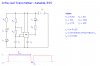
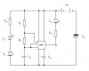
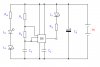
I am experimenting with using an infra-red LED and a corresponding photodiode to make use of remote control technology. Right now it's just an experiment, so I have set up a test circuit with both the transmitter and receiver, since I need to get a couple more batteries before I can use separate power supplies. The circuit diagram is attached.

I am using a 555 Timer IC to create a digital wave with a frequency of approximately 32kHz, where the mark time (Tm) is approximately 90% of the wave, also indicated in the attached diagram. I'm using this method to ensure that the LED is off for 90% of the time, so that it does not burn out when provided with an unusually high current (hopefully around 800-1000mA) which should help to boost the signal.

Anyway, the IR LED and photodiode are in very close proximity, so it is difficult to determine the range of the signal, but the red LED lights up as expected, and using a camera with IR capabilities I have also confirmed that the IR LED is coming on properly.

The circuit seems to work with the transmitter and receiver in close proximity, and with no damage to the IR LED, but I inserted an ammeter between R3 and L1 to check whether the current reaching the IR LED is as high as desired, to make sure that the 90% mark-time wave was indeed protecting the LED from a large current, but I found that the current passing through the IR LED was around 30mA, and the voltage across it was as low as 370mV.

Does anyone know why these values are so low? Is there a resistive component inside the IC which is limiting the current? And how might I get around this problem?


Just to rule out the battery as the problem, I measured it at 8.87V and it produced about 2.2A when I connected it directly to the ammeter.


Thanks in advance for any help.
 

Attachments

  • IR test.jpg
    IR test.jpg
    101.7 KB · Views: 604
Last edited:
Your circuit pulses, so you cannot use a multimeter to measure its voltages and currents. You must use an oscilloscope.

You shorted the battery with a current meter but the circuit doesn't work when the supply voltage is almost zero. The 'scope will show how low the battery voltage is dropping during each pulse.

A supply bypass capacitor will supply plenty of current for each pulse. Add one.

Your IR receiving LED seems to be connected oddly.
It can be reverse-biased (yours is forward-biased) then it leaks a small current when it receives IR.
Or it can have no bias and it generates a small voltage and current when it receives IR.

Usually a photodiode has an amplifier or it is in an IC that has an amplifier.
 
Looks like I'll have to find myself a cheap oscilloscope then.

How does a supply bypass capacitor work, how would I connect it, and what sort of capacitance rating would be appropriate?

Thanks for the prompt reply as usual audioguru.
 
The supply bypass capacitor charges slowly by the low current battery then the capacitor powers the load with as much current as it needs. It is a filter capacitor to prevent the supply voltage from dropping too much when the load demands a high current.

All battery powered circuits need a supply bypass capacitor.
 
Is this a special type of capacitor, or does its name simply come from its application? What sort of rating is suitable? Right now I only have a set of ceramic capacitors ranging from 10pF to 220nF.
 
Is this a special type of capacitor, or does its name simply come from its application? What sort of rating is suitable? Right now I only have a set of ceramic capacitors ranging from 10pF to 220nF.

It needs to be an eletrolytic, and in the hundreds or thousands of uF - depending on it's use.

For your use, try 220uF or 470uF.
 
Thanks for the advice guys, looks like I'd better order myself a set of electrolytic capacitors. Should this capacitor just be connected in series with the battery like in my updated circuit diagram?
 

Attachments

  • IR test.jpg
    IR test.jpg
    41 KB · Views: 985
Last edited:
If you connect a capacitor in series with the battery then the circuit will not have any current so it won't work. Besides, you connected your capacitor with backwards polarity.

The capacitor is a Bypass, it is parallel with the battery so it can charge then supply high current to the circuit when high current is needed.
 
you connected your capacitor with backwards polarity.

Whoops, so I did :eek:


The capacitor is a Bypass, it is parallel with the battery so it can charge then supply high current to the circuit when high current is needed.

Right, thanks for the explanation. I'm still not 100% clear on capacitors so I wasn't entirely sure how that worked.
 

Attachments

  • corrected.jpg
    corrected.jpg
    41.5 KB · Views: 297
Why would an oscilloscope have IR LEDs? If you want to check if IR LEDs are emitting, use a camera which can view IR.

If this isn't what you meant, I'd recommending creating your own thread with a suitable title, and a clearer explanation of what you are trying to achieve.
 
Last edited:
how can i view the ir rays emitted from the leds on the oscilloscope?

hi,
Use a matching IR detector with a load resistor connected to a low voltage supply say, 5V connect the scope across the IR detector.

Position the IR emitter close to the detector in order to get a strong signal.
 
That's not exactly "viewing the IR rays", that's viewing the resulting voltage across an IR detector when it encounters the signal.
 
That's not exactly "viewing the IR rays", that's viewing the resulting voltage across an IR detector when it encounters the signal.

You're splitting hairs, based on someone who obviously doesn't have English as his first language.

But I would say it's doing exactly that anyway, as much as an oscilloscope shows anything.
 
That's not exactly "viewing the IR rays", that's viewing the resulting voltage across an IR detector when it encounters the signal.


My post was intended for the OP, not for you to make another pointless post.

The poster asked how he could see the pulses on an oscilloscope, if he uses the method I described he can do just that.
 
My post was intended for the OP, not for you to make another pointless post.

The poster asked how he could see the pulses on an oscilloscope, if he uses the method I described he can do just that.

In case you haven't noticed, I am the OP. And I don't appreciate having my thread taken by someone else and then being notified when someone makes a rude and infantile comment about me. :mad:
 
Last edited:
You're splitting hairs, based on someone who obviously doesn't have English as his first language.

But I would say it's doing exactly that anyway, as much as an oscilloscope shows anything.

I'm not trying to split hairs, I was wondering if his goal is to "see" the IR being emitted, or whether it is indeed to monitor the voltage across a matching photodiode and thus get an idea as to the frequency of the signal, etc.
 
I only originally joined these forums to resolve my own queries, and I believe I've obtained sufficient information on them now. I've suffered enough disrespect for trying to help others on here, I don't think I'll bother any longer.
 
I'm not trying to split hairs, I was wondering if his goal is to "see" the IR being emitted, or whether it is indeed to monitor the voltage across a matching photodiode and thus get an idea as to the frequency of the signal, etc.

All an oscilloscope shows is light emitted from phosphur activated by a beam of electrons - it can only ever show a representation of anything - but a representation is all you need. As he specifically said 'on an oscilloscope' he obviously didn't mean he wnated to see the IR been emitted.
 
I only originally joined these forums to resolve my own queries, and I believe I've obtained sufficient information on them now. I've suffered enough disrespect for trying to help others on here, I don't think I'll bother any longer.

hi giftiger.
No one is disrespecting you.
What you should appreciate most of us try to answer the question based on our experience in knowning that the posters first language is not English and trying to figure out what he is really asking.

There are a small number of people on this Forum who's opinions/comments I value and trust, at this time you are not one of them.
Dont take that as an insult, its not intended in that way.

It would be a sad loss if you quit because someone has criticised you.:)

You should have told the other 'OP' not to hijack your thread.

Regards
 
Last edited:
Status
Not open for further replies.

Latest threads

New Articles From Microcontroller Tips

Back
Top