I see many posts of people wanting to drop AC line voltage to 5VDC to run some circuit..."without using a transformer". I think they're trying to save either money or space. Though I have done that, I find that in the long run I don't really saved either...and I've added the risk of a non-isolated supply. It was usually to add a small low voltage source inside a devise that already had line-voltage internally and didn't want the add a cheap, external wall-wart plus internal regulator circuit.
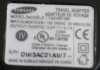
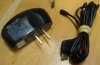
When cell phone manufacturers started using switch-mode power supplies in their chargers I found the perfect source for small, isolated, wide range AC voltage, relatively high output current power supplies.
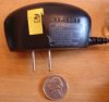
OK this is sort of an "instructable".") I can find a variety of SMPS chargers at places like Goodwill for $0.69 USD. You can find them by noting how light they are for the labeled current output, compared to the weight of standard wall-warts with line frequency transformers with a similar current output.
I can find a variety of SMPS chargers at places like Goodwill for $0.69 USD. You can find them by noting how light they are for the labeled current output, compared to the weight of standard wall-warts with line frequency transformers with a similar current output.
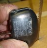
1. Cut off the output cord at the case.
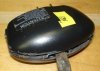
2. Use a bandsaw, Dremel with a saw blade, or hand scroll saw to cut through the case along the glue line. Cut just enough to break through on three sides. Be very careful not cut any deeper, as you may cut into the circuit board.
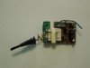
3. Use a flat blade screwdriver to pry the case halves open.
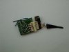
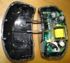
4. Remove your small, step-down, isolated SMPS.
There are many variations on the cases, complexity, and internal connections to the line plug contacts, but the same technique has always worked for me.
I have even found some that used standard controller ICs, and have been able to tweak the output sensing voltage divider to get a different regulated output voltages.
The down side...there is always one... you need to be creative on how to safely mount the PCB.
Ken
When cell phone manufacturers started using switch-mode power supplies in their chargers I found the perfect source for small, isolated, wide range AC voltage, relatively high output current power supplies.
OK this is sort of an "instructable".
I can find a variety of SMPS chargers at places like Goodwill for $0.69 USD. You can find them by noting how light they are for the labeled current output, compared to the weight of standard wall-warts with line frequency transformers with a similar current output.1. Cut off the output cord at the case.
2. Use a bandsaw, Dremel with a saw blade, or hand scroll saw to cut through the case along the glue line. Cut just enough to break through on three sides. Be very careful not cut any deeper, as you may cut into the circuit board.
3. Use a flat blade screwdriver to pry the case halves open.
4. Remove your small, step-down, isolated SMPS.
There are many variations on the cases, complexity, and internal connections to the line plug contacts, but the same technique has always worked for me.
I have even found some that used standard controller ICs, and have been able to tweak the output sensing voltage divider to get a different regulated output voltages.
The down side...there is always one... you need to be creative on how to safely mount the PCB.
Ken
Attachments
Last edited: