Hello, excuse me if this is out of forum but i wasn't allowed to enter to the electronic theory forum, maybe because i'm still too new.
I'm working on a lab report of this equivalent circuits, i'm almost done but there's a quiestion about the consumed power for different values of load.
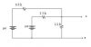
The practice is this, yo have a circuit and you determine the Thevenin equivalent & the Norton equivalent theorically and then you put three different values of load one by one, they are 0.5 kΩ, 1k and 1,5kΩ, to calculate the power consumed by them. after that, you do the same but in the project board, practically.
This is what happens:
When I change the load from 0.5k to 1kΩ the power consumed increases, but when I change it again to 1,5kΩ from 1kΩ it decreases, not so much but it decreases, and the question that says "What can you say about the power consumed for different values of load?" is getting a little tough for me to answer, because I don't know why the power behaves like that.
I hope you can help me out with this.
I'm working on a lab report of this equivalent circuits, i'm almost done but there's a quiestion about the consumed power for different values of load.
The practice is this, yo have a circuit and you determine the Thevenin equivalent & the Norton equivalent theorically and then you put three different values of load one by one, they are 0.5 kΩ, 1k and 1,5kΩ, to calculate the power consumed by them. after that, you do the same but in the project board, practically.
This is what happens:
When I change the load from 0.5k to 1kΩ the power consumed increases, but when I change it again to 1,5kΩ from 1kΩ it decreases, not so much but it decreases, and the question that says "What can you say about the power consumed for different values of load?" is getting a little tough for me to answer, because I don't know why the power behaves like that.
I hope you can help me out with this.
Last edited: