Hey guys
I've learnt so much here already but am a little stuck on the details of the code below...
I am a beginner so please have some patience with me... thanks
Could someone answer the following in red?
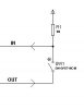
RB0 - RB3 have resistors to +ve
...
KEY_PORT Equ PORTB ;keypad port
KEY_TRIS Equ TRISB
Col1 Equ 0 ;pins used for keypad inputs
Col2 Equ 1
Col3 Equ 2
Col4 Equ 3
...
SetPorts bsf STATUS, RP0 ;select bank 1
movlw 0x0F ;set keypad pins
movwf KEY_TRIS ;half in, half out
movwf TRISB
.........
Chk_Keys movlw 0x00 ;wait until no key pressed
movwf KEY_PORT ;set all output pins low
movf KEY_PORT, W
andlw 0x0F ;mask off high byte
sublw 0x0F
btfsc STATUS, Z ;test if any key pressed
goto Keys ;if none, read keys
call Delay20
goto Chk_Keys ;else try again
(With the resistors on the inputs, that makes the inputs 1 all the time right?
Then if a key is pressed, it takes a 1 to the corresponding output changing the value, thereby changing the status of z?
)
Keys call Scan_Keys
movlw 0x10 ;check for no key pressed
(Dont understand the 0x10 above?)
subwf key, w
btfss STATUS, Z
goto Key_Found
call Delay20
goto Keys
Key_Found movf key, w
andlw 0x0f
call Key_Table ;lookup key in table
movwf key ;save back in key
return ;key pressed now in W
Scan_Keys clrf key
movlw 0xF0 ;set all output lines high
movwf KEY_PORT
(will it be b'11111111' ? )
movlw 0x04
movwf rows ;set number of rows
bcf STATUS, C ;put a 0 into carry
Scan rrf KEY_PORT, f
bsf STATUS, C ;follow the zero with ones
(Dont understand the above exactly? )
;comment out next two lines for 4x3 numeric keypad.
btfss KEY_PORT, Col4
goto Press
incf key, f
btfss KEY_PORT, Col3
goto Press
incf key, f
btfss KEY_PORT, Col2
goto Press
incf key, f
btfss KEY_PORT, Col1
goto Press
incf key, f
decfsz rows, f
goto Scan
Press return
(What im confused about is this...
where and how is the program checking for a 1 or 0 on portb to decide which key has been pressed?
The resistors make RB0-3 a value of 1 correct? so then having RB4-7 as an output does what?
)
Im trying to understand this at the most detailed level so I can learn how and why, which will lead me to be able to apply the knowledge and not just have a solution for my current problem")
Thanks for all your explanation and patience
I've learnt so much here already but am a little stuck on the details of the code below...
I am a beginner so please have some patience with me... thanks
Could someone answer the following in red?
RB0 - RB3 have resistors to +ve
...
KEY_PORT Equ PORTB ;keypad port
KEY_TRIS Equ TRISB
Col1 Equ 0 ;pins used for keypad inputs
Col2 Equ 1
Col3 Equ 2
Col4 Equ 3
...
SetPorts bsf STATUS, RP0 ;select bank 1
movlw 0x0F ;set keypad pins
movwf KEY_TRIS ;half in, half out
movwf TRISB
.........
Chk_Keys movlw 0x00 ;wait until no key pressed
movwf KEY_PORT ;set all output pins low
movf KEY_PORT, W
andlw 0x0F ;mask off high byte
sublw 0x0F
btfsc STATUS, Z ;test if any key pressed
goto Keys ;if none, read keys
call Delay20
goto Chk_Keys ;else try again
(With the resistors on the inputs, that makes the inputs 1 all the time right?
Then if a key is pressed, it takes a 1 to the corresponding output changing the value, thereby changing the status of z?
)
Keys call Scan_Keys
movlw 0x10 ;check for no key pressed
(Dont understand the 0x10 above?)
subwf key, w
btfss STATUS, Z
goto Key_Found
call Delay20
goto Keys
Key_Found movf key, w
andlw 0x0f
call Key_Table ;lookup key in table
movwf key ;save back in key
return ;key pressed now in W
Scan_Keys clrf key
movlw 0xF0 ;set all output lines high
movwf KEY_PORT
(will it be b'11111111' ? )
movlw 0x04
movwf rows ;set number of rows
bcf STATUS, C ;put a 0 into carry
Scan rrf KEY_PORT, f
bsf STATUS, C ;follow the zero with ones
(Dont understand the above exactly? )
;comment out next two lines for 4x3 numeric keypad.
btfss KEY_PORT, Col4
goto Press
incf key, f
btfss KEY_PORT, Col3
goto Press
incf key, f
btfss KEY_PORT, Col2
goto Press
incf key, f
btfss KEY_PORT, Col1
goto Press
incf key, f
decfsz rows, f
goto Scan
Press return
(What im confused about is this...
where and how is the program checking for a 1 or 0 on portb to decide which key has been pressed?
The resistors make RB0-3 a value of 1 correct? so then having RB4-7 as an output does what?
)
Im trying to understand this at the most detailed level so I can learn how and why, which will lead me to be able to apply the knowledge and not just have a solution for my current problem
Thanks for all your explanation and patience