Continue to Site

Welcome to our site!

Electro Tech is an online community (with over 170,000 members) who enjoy talking about and building electronic circuits, projects and gadgets. To participate you need to register. Registration is free. Click here to register now.

  • Welcome to our site! Electro Tech is an online community (with over 170,000 members) who enjoy talking about and building electronic circuits, projects and gadgets. To participate you need to register. Registration is free. Click here to register now.

Newbie Needing HELP with Circuit to Stripboard layout?

Status
Not open for further replies.

Schematicsman

New Member
Hi there everyone :)
I have been scratching my head on how to layout circuit diagrams to strip and how to start design and or planning on paper.

I would like to really learn properly from scratch step 1.....Step 10 ... from paper planning to laying out on stripboard in great detail with the help of you guys...


--------------------------------------------------------------------------------------
I love these prototyping boards ,great for me to learn electronics..

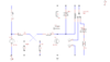
I 'am trying to transfer the multiplexing 2 digit 7 segment Common Anode individual displays using 14x 220 Ohm Resistors and (2 x PNP BC557 Transistors w/ 1Kohm Resistors connected to the Base_Leg) circuit I wired up on Breadboard to laying out on Stripboard..

IF ANYONE CAN HELP ME GET MY HEAD AROUND THIS, I WILL BE SO GREATFULL .
 
Welcome to ETO!
Have you tried Pebble (works with Firefox browser)?
 
I just drop components in loosely to start with, main or highest pin counts first.

Look at the spacing and relationships between them, allowing for what connects where and what passive components have to fit between or near the other parts. Move things about as required until it looks reasonable, then start soldering sockets for ICs and cutting tracks with a small drill bit to separate different items.

Use plenty of space for your first designs, you will soon get used to how much is needed and adjust things in future designs to be more compact.

I'd allow a minimum of five holes between the closest two non-connected component leads or pins; that allows for the track to be cut at the centre hole and still two connected points where you can fit connecting wires to each part.

Use seven holes between, or more, to give plenty of space on non-critical layouts.
 
Last edited:
Last time I used strip board, I did the schematic in Eagle then layed the board out with the bottom layer all in one direction so, anything on the top layer was either a component or link. I placed holes where strips needed to be broken. Messy but it worked for me.

Mike.
Edit, this was about 10 years ago, now, I just get (double sided) boards made.
 
When doing strip board (Vera board as I know it) I use the following two software packages.
https://www.tinycad.net/ - Tinycad to draw the schematic with and then
https://veecad.com - to do the board layout.
You will find many "Google search" videos and pages on how these two packages work together.
 

Attachments

  • VeeCad.png
    VeeCad.png
    15.4 KB · Views: 210
  • TinyCad.png
    TinyCad.png
    10.1 KB · Views: 206
Status
Not open for further replies.

Latest threads

New Articles From Microcontroller Tips

Back
Top