Electro Tech is an online community (with over 170,000 members) who enjoy talking about and building electronic circuits, projects and gadgets. To participate you need to register. Registration is free. Click here to register now.
Welcome to our site! Electro Tech is an online community (with over 170,000 members) who enjoy talking about and building electronic circuits, projects and gadgets. To participate you need to register. Registration is free. Click here to register now.
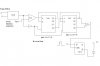
hi, helpers ...below is my diagram. It counts but there is a slight problem with the D-flipflop.Led just would not go off :shock: ...hmmm...is there any other chip besides the D flipflop that i can use?
hi, helpers ...below is my diagram. It counts but there is a slight problem with the D-flipflop.Led just would not go off :shock: ...hmmm...is there any other chip besides the D flipflop that i can use?
What is wrong with the D flip flop? A rising edge on CLK input (from your and gate) will transfer your input (logic 1) to your output and logic 0 to the compliment output Q(bar)
1) measure the Q(bar) output, if it is not zero volts then you have a problem with your logic.
2) if it is zero then maybe your LED is connected backwards or maybe your resistor is too large of a value. Use something close to 330 Ohms.
I don't think the D type flip flop does what you are expecting it to do. From what I can see when the Flipflop gets a clock it outputs a 0 to turn on th LED. The way its set up it will never change after that. It sounds like the the Flipflop is working but your circuit need modification to do what you want it to do. If you explain what you need the circuit to do we can help more.
I don't think the D type flip flop does what you are expecting it to do. From what I can see when the Flipflop gets a clock it outputs a 0 to turn on th LED. The way its set up it will never change after that. It sounds like the the Flipflop is working but your circuit need modification to do what you want it to do. If you explain what you need the circuit to do we can help more.
yes this is true.. there is a problem with the authors logic circuit.
I believe the author wants to turn on the LED if a counter has counted to 100 (getting its count pulses by an asynchronous source) in less than 1 minute (which is generated from a one shot timer elsewhere).
I had suggested a method to pursue but I am not sure if the author is doing that or not. This particular ckt is just the LED piece of it. I know all this because this discussion started in another thread.
The author should draw the whole thing together so we can look at the original requirements and find out what needs changed. (hint hint)
This site uses cookies to help personalise content, tailor your experience and to keep you logged in if you register.
By continuing to use this site, you are consenting to our use of cookies.

")