MrDEB
Well-Known Member
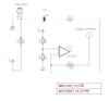
here is the website that suggest that the LM358 module may have too much "noise" and less accuracy.

 circuitdigest.com
Measure Sound/Noise Level in dB with Microphone and Arduino
In this project we will use a normal Electret Condenser microphone with Arduino and try measuring the sound or pollution level in dB as close as possible to the actual value.
circuitdigest.com