Continue to Site

Welcome to our site!

Electro Tech is an online community (with over 170,000 members) who enjoy talking about and building electronic circuits, projects and gadgets. To participate you need to register. Registration is free. Click here to register now.

  • Welcome to our site! Electro Tech is an online community (with over 170,000 members) who enjoy talking about and building electronic circuits, projects and gadgets. To participate you need to register. Registration is free. Click here to register now.

New Project on Obsoleted Part

Status
Not open for further replies.
I received the display a few days ago, got it all soldered in and... Nothing. It doesn't display anything. No backlight, no dark images, just nothing. I find that kind of hard to believe. Makes me wonder if I messed something up.

How I did it was I removed the old display out of the board from the 64128E and soldered in the new board. I did this because the pins matched up perfectly and the pinout was as I displayed above. So I'm going to look it over again tomorrow and see if I'm missing something. The only thing I did different was I soldered pins 17 and 18 straight through but that should have gone to the LED which isn't hooked up....
 
I wish you had been able to test it before putting it in the old board. Any good pics that you can post?
 
120053
120054


So a couple things. my solder joints don't look awesome but I think they work, there is still some flux from the previous connection from the factory and on the closeup look at the soldered pins it looks like the screen is burned but that is just the plastic holder I transferred from the old board - it was pretty tight getting in there. Hopefully the pictures are relatively clear, I had to downsize them a bit to get them in here. It is really nice to have a forum you can just drag and drop photos into, I hate when you have to upload them elsewhere and insert the link.
 
The pictures are not clear and close enough to tell whether the soldering is ok, but maybe it is. Backing up a minute, differentiate two connectors on the display unit (either the new or old unit) - I marked them A and B below:

120057


Now, go back to the data sheets and compare the pin connections, from schematic diagrams, for each connector A and B for both displays. I thought that you would be doing that for the A connector and, if they matched, replace the screen at that level - that was the hope for the COG screen since we knew that both used the same driver chip.

Did you buy two new displays? Did you get the pinouts for the 18 pin B connector for the new display?
 
I thought about buying two but only bought one. I guess I'm not sure what you mean by differentiate between the two. The A pins are on the new display, the B pins are what was originally soldered together on the unit from the factory. I used the line drawing I made showing where the pins should go to verify (check continuity) that the 16 pins were a direct pass through from A to B. I should have just soldered connections to the individual leads to test first using jumper wires but I was too eager and thought it would work perfectly first time!

The 64128COG I received looked like this :
120059

If you look close it is just the glass display with 30 pins. Pin number 1 starts on the right and goes to 30 on the left.

I connected it to the PCB that came with the 64128E to give me something that looked like this:
120058


The only pins that I think I am concerned with which I had drawn out were pins 1-16 on the PCB which by the below diagram shows going from left to right bottom to top 1-18. I connected 17 and 18 even though they won't be used, these should only give power to the LED for the old backlight which I did not connect to the PCB.

These are the pins on the PCB:
120061

I do not know anything about the main board that came with the unit, I have been making assumptions that it is a direct match to the above diagram if that makes sense. So I am assuming the main board pin 1 is Vss and pin 2 is Vdd based on the original 64128E requiring pin 1 to be Vss and pin 2 to be Vdd. The original 64128E was soldered directly to the main board like I have in the picture I shared using pins soldered at both ends.


Here is the diagram I drew showing what I think the pinout should be. I checked continuity on the PCB I soldered the display to and they appeared to be a direct pass through. For instance if I check pin 1 for the display and pin 16 on the PCB or pin 5 on the display and pin 12 on the PCB I have continuity etc.

Display on left PCB (64128E original display) on right
120062


Could there be an issue with pins 17-30 being connected? Here is the full pin labels for the LCD module:
120063
 

Attachments

  • 1566398684568.png
    1566398684568.png
    55 KB · Views: 162
This is frustrating because it is sometimes difficult to communicate using these messages. I think that you gave it a shot and maybe it is best to leave it at that. I am however, fine discussing it further.

Consider the photo below, and for the moment, please do not go further about 16 pin and what you drew and other things because it is confusing me and I am too stupid to follow:

120080


You started with the board outlined in grey and marked 'C' on the original equipment and that board, which contained the LCD screen WAS the 64128E . I understand that you replaced the screen - just put that aside for the moment so that we can get on the same page.

That board, outlined in grey and marked 'C' is the original 64128E and it has an 18 pin (not 16 pin) connector denoted by 'B' in the photo. It also has a 30 pin connector denoted by 'A' in the photo. That is my understanding.

You unsoldered the 18 pin connector, which freed the 64128E from the equipment board that has the buttons on it and note that the board with the buttons on it is not part of the 64128E and it is part of your equipment. Then you unsoldered the 30 pins for the screen at 'A'. Then you re-soldered the NEW 64128COG (which does not have its own board and only has the 30 pins on the display) on to the 30 pin connector on the original board and at 'A'. Finally, you put the modified 64128E board back onto the equipment board at the 18 pin connector. It does not work.

If that is not correct, then, disregard what follows and explain what you did again because I have read it several times and it seems like my description is correct.

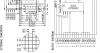
If you are still reading, go to the 64128E schematic that I posted in #16.

Go to page 3. Note that the 18 pin connector is shown with the 18 signals. The connector for those 18 signals is 'B'. Note also that the 'A' connector is shown in the drawing on page 3, but that the signals on the 30 pin connections are not shown on page 3, but they are shown on page 6.

Here is an important point, back on page 3, there is a lot of stuff going on between the 'A' and 'B' pins. That "stuff" is represented by the block diagrams and one of those block diagrams is the KS0713 controller (also note the serial/paralell switch). Ask yourself where the KS0713 controller (which is an IC) is at on the 64128E. When you removed the screen, did you see anything else on the 64128E board? My guess is that you did and one of the things that you saw was the KS0713 controller IC ( I suppose it could have been on the back of the LCD screen, but I doubt it). So, on this point, pictures of the 64128E board after removal of the LCD screen (the 30 pin connection marked as 'A', would be valuable.

With that in mind, look at the schematic for the 64128COG from the link that I also posted in #16. The 30 pins are defined on page 3. Notice that there is no 18 pin connector like on the 64128E. There is also no block for the KS0713 controller because, unlike with the 64128E, the KS0713 is embedded in the glass of the screen (chip-on-glass). These are critical points to understand if you want to replace the 64128E with the 64128COG.

So, what I thought that you would do, would be to make your own board, using the 64128COG that would replace the 64128E board. That is why I showed you the pic in post #31,

What is involved in that? Let's assume that the original 64128E had the switch in parallel mode and so the new board would contain the 64128COG and the capacitors shown in the top of page 6 of the 64128COG data sheet. Note that there are 14 signals defined there and you can add 3v and GND for a total of 16 signals.

Those 16 signals would be routed to an 18 pin connector on the new board so that it will fit on the equipment board (again, the one that has the buttons). Look at those 16 signals and notice that they all correspond to signals on the 64128E board schematic. The remaining two signals (to make it 18) are the back light +/-. Apparently, there is no back light on the 64128COG but that is a separate issue.

That is what the replacement board would need to do in my opinion. You can't simply swap out the LCD screens at the 30 pin connector and keep the old 64128E board because there is other stuff on there... that is what I am thinkin and of course, if I could see all of this rather than speculate, I might change my thinking.

Why go through all that trouble? Well, again, you have no control whatsoever over the firmware, so making a new board with the 64128COG at least means you are using the same KS0713 controller as the 64128E.

Remember that, back in post #31, I asked if you were sure you wanted to do this.
 
Last edited:
Status
Not open for further replies.

New Articles From Microcontroller Tips

Back
Top