Continue to Site

Welcome to our site!

Electro Tech is an online community (with over 170,000 members) who enjoy talking about and building electronic circuits, projects and gadgets. To participate you need to register. Registration is free. Click here to register now.

  • Welcome to our site! Electro Tech is an online community (with over 170,000 members) who enjoy talking about and building electronic circuits, projects and gadgets. To participate you need to register. Registration is free. Click here to register now.

Neeed some help with dual PIR sensor circuit

Status
Not open for further replies.
hi,
I have added the relay 12V supply link, also shown an option for switching the 'high' side rather than 'low' side of the lights.

E
 

Attachments

  • Pir_circuit_4.jpg
    Pir_circuit_4.jpg
    45.7 KB · Views: 624
The relay coil needs current flowing thru the coil to operate.
 

Attachments

  • Pir_circuit_4.jpg
    Pir_circuit_4.jpg
    53.8 KB · Views: 807
Hello, guys...

I was looking for something like this, but only one sensor and one stripe.

Could one (whiteangel?) be so kind and write the final list of elements and possibly new sheme, if any changes in the final work, please?

Already have the sensor (HC-SR501) and stripes (5050 SMD RGB)

Thnx
 
hi Roger,
The circuit will be basically the same as post #23.
I will update an post
E
 
hi Roger,
Try this circuit, its for one PIR.
NOTE:
Set the 's' for sensitivity and 't' for the ON time of the PIR [ marked pots mounted on the PIR PCB]

Allow about 2 minutes settling time for the PIR after powering up.

E
 

Attachments

  • Pir_circuit_4.jpg
    Pir_circuit_4.jpg
    40.9 KB · Views: 361
Sorry, Ian. I know hijacking is not good. Wont happen anymore.

Thank you Eric.
How many watts should resistors be?

R.
 
Sorry, Ian. I know hijacking is not good. Wont happen anymore.

Thank you Eric.
How many watts should resistors be?
R.

hi,
I would use 0.25W [ or higher if that's what you have]
E
 
Hello.

I noticed that when HC-SR501 goes off, it has a delay to turn on again after 6-7 seconds. (wawing infront of the sensor)

Is it possible to modify HC-SR501 to switch on immediately when motion is detected (after it goes off at timer)
 
hi R,
That dead time after an active ON period is called the blockade time, which appears to be fixed.?

Would repeat triggering of the PIR be acceptable for your application.?
In other words the PIR output is High/On while movement is being detected.?

E
 

Attachments

  • A001.gif
    A001.gif
    12.6 KB · Views: 252
  • A003.gif
    A003.gif
    153.7 KB · Views: 276
Last edited:
Would repeat triggering of the PIR be acceptable for your application.?

Hi, Eric.

I guess so.. it is ment to be for led lights in the bathroom. My wife always forget to switch off the lights :)

I would like to set the blockade time to minimum.
I tried rotating trimmers, but couldn't get it.

Thank you,
R.
 
hi Roger,
The blockade' time as the spec describes it, is fixed.
Thanks for the video showing that modification for the 'blockade' time.

Pleased to hear its working.
E
 
hi Eric.

Thnx!

I was expecting a hack like this.

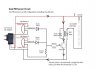
Now, when the timer goes off and when the motion is active, the light goes on immediately, ~0.1 sec (before 5-6 sec.)

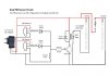
The second idea was to put two sensors in parallel with slightly different timer delay.
That I will probably implement anyway, to cover more area. (There are shower doors, that could block the first sensor)

R.
 
hi,
You could add a second sensor by using the original dual PIR circuit, posted earlier.
Modify the 'blockage' time on the second sensor to suit the app.
E

EDIT:
Note the direction sensitivity.
A001.gif
 

Attachments

  • Pir_circuit_4.jpg
    Pir_circuit_4.jpg
    49.4 KB · Views: 260
Last edited:
Hello Eric.

Thank you for clarification of direction sensor sensitivity.

If I want to use 5V input (for other project), what do I need to change in the circuit?
I already have 5V relay.

Edit:
Actually I connected as it is and it is working, but just want to be sure.


R.
 
Last edited:
hi Roger,
That PIR unit will work with a Vsupply of 5v thru 20v.
It has an board 3.3v regulator, so the output swing is always 0v to +3v
E
A001.gif
 
Status
Not open for further replies.

Latest threads

New Articles From Microcontroller Tips

Back
Top