Continue to Site

Welcome to our site!

Electro Tech is an online community (with over 170,000 members) who enjoy talking about and building electronic circuits, projects and gadgets. To participate you need to register. Registration is free. Click here to register now.

  • Welcome to our site! Electro Tech is an online community (with over 170,000 members) who enjoy talking about and building electronic circuits, projects and gadgets. To participate you need to register. Registration is free. Click here to register now.

Need Transistor Recommendation for Conar 212 Transistorized VOM

Status
Not open for further replies.

BrandonD

New Member
This is a great meter when it works. The transistors are for the meter circuit of the Conar 212 TVOM designed in the 1970s.

I need an accurate recommendation for low power N-channel JFET’s, that are available to buy. I have the manual but it does not specify.
The meter was working before. 9 volts hit it (my goof), not an overloaded test mistake. I came to the conclusion that it is a transistor because now when I turn it on, the needle hits the right pin and stays there, regardless of settings.

The movement is 200 microamps, and the numbers are linear on the dial (except for ohms), so I assume the transistors need to be linear in the range used.

On the transistors it says TS20 and has a Motorola “M”.

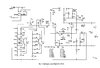
Circuit diagram follows.

Please don’t guess if you are not expert!

Please do tell us why you made the recommendation you did.

Thank you,

Brandon
 

Attachments

  • Schematic  Conar 212 TVOM cr.jpg
    Schematic Conar 212 TVOM cr.jpg
    378 KB · Views: 224
rjenkinsgb
I appreciate this. I also received a recommendation to use a J112, but I wouldn't know the difference.
Is either or both linear below 200 microamps?
I know the meter had about a 12 Mohm input.

Brandon
 
The movement is 200 microamps, and the numbers are linear on the dial (except for ohms), so I assume the transistors need to be linear in the range used.
Is either or both linear below 200 microamps?

I think that your understanding of the operation of the FETs in this circuit is not quite correct.

They are configured as a basic differential amplifier.
The 200uA meter is connected between the sources of the two FETs.
My best estimate is that the FETs will be conducting around 6 or 7 mA during normal operation when the meter is reading zero.
When reading full scale, the diff-amp will be unbalanced so that there is about a 1 volt difference between the sources of the two FETs, causing 200uA to flow through the meter movement.
The FETs themselves are always conducting more than 200uA, so linearity in that area and below is not a problem.

So, I suggest the you buy some FETs, J112 or J201, or 2N3819 if you like.
As suggested by schmitt trigger, if you buy more that two FETs, you could try matching them, I don't know how critical a matched pair is in this circuit.

**Idea**
It is possible to buy two matched FETs in one package, you could try that approach, but it may be a bit of overkill for this application. (Sorry but I dont know any numbers for matched FETs just off the top of my head).

JimB
 
I just did a bit of googling and found a copy of the manual for this VOM.

In that manual, the parts list had been annotated by someone and the FETs are named as 2N5457.
If you can find those, that may make life easier in repairing your meter.

JimB
 
Wow I did not expect to get so much good advice so fast! Thanks everyone.
Looks like I can resurrect it. :D

JimB, you are right, the theory of the circuit was beyond my training. I know enough to follow audio equipment schematics and make parts modifications that sound better, and play with loudspeaker crossovers. I am impressed you found the manual with the 2N5457 note.

I think I will buy 3 each of two types, to cover any problems, they are cheap enough.


Brandon
 
Last edited:
the meter driver FETS are in source follower configuration... any low gate current FET should work as long as they're matched for Idss.
 
Status
Not open for further replies.

Latest threads

New Articles From Microcontroller Tips

Back
Top