Hello. I need a reliable thyristor firing circuit design for an industrial application here at work. I work in a medium density fiberboard (MDF) facility. The application is for a "Rapper Control Module" on an Electrostatic Precipitator. This "ESP" is basically an electrically charged filter which removes the dust & soot from the exhaust gases of a large furnace. As the electrically charged filter rods get coated with soot, every once in a while a "rapper" will activate which knocks the soot off the rods and allows it to fall into a waste collection system. The "Rappers" are basically a hollow cylinder mounted vertically at the very top of the ESP and have a coil at the bottom of the rapper. When an SCR fires the discharged energy causes a large solid weight inside the cylinder to move upwards and "rap" the top off the cylinder. This in turn causes the rod to vibrate and the excess soot to fall off keeping the rod clean. There are many rappers in the ESP. Each one gets fired individually over a preset firing order and adjustable time delay.
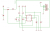
The rapper control module or RCM is an old design which is constructed of relays, timers, mechanical stepper motor, etc. These units have been failing alot recently. The relays inside are obsolete and we can't get exact matches anymore. To make them work we would have to install different design relays with different bases etc. Basically the units aren't reliable anymore. The OEM wants BIG$$$ to covert to the latest greatest. For what the units do, we've decided we want to attempt to design our own RCM for much less $$$. Please see the attached files (diagrams & pictures - 6 pgs). The charging & timing system design we can take care of this. What we need help with is a reliable circuit to fire the SCRs (NTE5547) into the rapper coils (approx 1.2-1.8ohms). We would like to use 24VDC for the firing cct as this is readily available. However I'm sure we could work with other voltages as well. Any design diagrams or tips would be much appreciated. Thanking everyone in advance for any assistance given. Thank you. View attachment SCR post1(1).pdf
.JPG")
.JPG")
The rapper control module or RCM is an old design which is constructed of relays, timers, mechanical stepper motor, etc. These units have been failing alot recently. The relays inside are obsolete and we can't get exact matches anymore. To make them work we would have to install different design relays with different bases etc. Basically the units aren't reliable anymore. The OEM wants BIG$$$ to covert to the latest greatest. For what the units do, we've decided we want to attempt to design our own RCM for much less $$$. Please see the attached files (diagrams & pictures - 6 pgs). The charging & timing system design we can take care of this. What we need help with is a reliable circuit to fire the SCRs (NTE5547) into the rapper coils (approx 1.2-1.8ohms). We would like to use 24VDC for the firing cct as this is readily available. However I'm sure we could work with other voltages as well. Any design diagrams or tips would be much appreciated. Thanking everyone in advance for any assistance given. Thank you. View attachment SCR post1(1).pdf