Continue to Site

Welcome to our site!

Electro Tech is an online community (with over 170,000 members) who enjoy talking about and building electronic circuits, projects and gadgets. To participate you need to register. Registration is free. Click here to register now.

  • Welcome to our site! Electro Tech is an online community (with over 170,000 members) who enjoy talking about and building electronic circuits, projects and gadgets. To participate you need to register. Registration is free. Click here to register now.

need to add temperature display using LM335

Status
Not open for further replies.

prosound90

New Member
hi guys

i think it will be easier to put this in a new topic instead of the 2 pages topic for the clock AN590.

the clock is working fine thanks to your help .

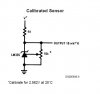
i need to add temperature display , i have a bunch of LM335 i bought a

long time ago and i like to interface it with the 16F877.

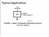
i hve a schematic that i downloaded from the internet ,dose this one work???, (i know it use LM34).


i have AN0,AN2,and AN3 available ,

do i need to use an OPAMP for the signal or it can be inerfaced directly

if any one have a schematic please post it.

iam thinking of a scale from -20C to 50C or ,and 0-120 F

thanks for your help.
 

Attachments

  • thermoschem.jpg
    thermoschem.jpg
    9.2 KB · Views: 2,617
i am not understanding what you are outputting ..
you only need to read analog from the device..
 
thats a shcematic from somebody was using this interface with a 16F628 and a LCD i dont know if it works or not ...thats why iam asking if it works like that .

i think the output is for (V) refrance.
 
iam going to use your schematic with LM335

in my project .


is it going to be ok to use the VDD for refrence for the scale that i need?
 
Sorry for butting in, on your thread prosound90. I am working on a similar req. for my project and was planning to use an LM35.

On the datashet the circuit below gives full range -55C to +150C
Could I confirm:
> If V+ is 5V V- is ground R1 should be 1K Ohms? ( -V == -5V? :oops:)
> I could hook up Vout directly to ADC pin on 16f877?

Thanks
Spiros
 

Attachments

  • lm35.gif
    lm35.gif
    6.9 KB · Views: 2,335
prosound90 said:
iam going to use your schematic with LM335

in my project .


is it going to be ok to use the VDD for refrence for the scale that i need?
so V+/.005
or your V+/.004 =R1..
might as well not bring I to the max..
even 1 mA would work great ..
 
spirosd said:
Sorry for butting in, on your thread prosound90. I am working on a similar req. for my project and was planning to use an LM35.

On the datashet the circuit below gives full range -55C to +150C
Could I confirm:
> If V+ is 5V V- is ground R1 should be 1K Ohms? ( -V == -5V? :oops:)
> I could hook up Vout directly to ADC pin on 16f877?

Thanks
Spiros
do you have -5V available ..if not, dont use a resistor..
if you do , -5/50 microamps = 10K ohms..

i dont think yours needs a resistor for 2 centegrade to 150 C..

but to get the full range they recommend..>
Choose R1 = −VS/50 µA
V OUT=+1,500 mV at +150°C
= +250 mV at +25°C
= −550 mV at −55°C

I could hook up Vout directly to ADC pin on 16f877?
i dont see why not..
 

Attachments

  • lm35_210.jpg
    lm35_210.jpg
    15.1 KB · Views: 1,977
Thank you for your reply williB.

I need the negative temps so I have to try and use the full range.

williB said:
do you have -5V available ..if not, dont use a resistor.. if you do , -5/50 microamps = 10K ohms..

I do not have -5V available, so I presume I can not use that circuit.

The datasheet also has this circuit .... the -ve output voltage confuses me. How would I use that circuit with a pic?

Thanks
Spiros
 

Attachments

  • lm35_2.gif
    lm35_2.gif
    5.4 KB · Views: 1,865
im curious about this, if the LM35 is placed in a freezer, will the voltage output immediately drop to 0 V?

Im having a strange problem, no matter where i place my LM35 the temperature range is always between 25 C to 35 C.

I grounded my -Vs in this case, since i dont require any negative voltage
 
fabbie said:
im curious about this, if the LM35 is placed in a freezer, will the voltage output immediately drop to 0 V?

Im having a strange problem, no matter where i place my LM35 the temperature range is always between 25 C to 35 C.

I grounded my -Vs in this case, since i dont require any negative voltage
where did you ground the LM35..??which picture?
 
hi

i want to aske a diffrent qusetion now?

what consederation should i keep in mined when adding an analoge reading to my project you know(a clock) and iam adding a temeperature reading to it.

because the ADC takes long time to get result iam worried about the clock losing time as it has to stop to get ADC reading.

what do you recomend the interuput way or A CALL to the ADC ,(read,display,then go back to time count)

do i have to compensate for the time that the ADC use so the clock dose not loose count ?

can i use the same (tmr0 for both) or its better to use (tmr1 free running for the time on 32khz) ? and 4mhz for the PIC.

thank you
 
prosound90 said:
hi

i want to aske a diffrent qusetion now?

what consederation should i keep in mined when adding an analoge reading to my project you know(a clock) and iam adding a temeperature reading to it.

because the ADC takes long time to get result iam worried about the clock losing time as it has to stop to get ADC reading.

what do you recomend the interuput way or A CALL to the ADC ,(read,display,then go back to time count)

do i have to compensate for the time that the ADC use so the clock dose not loose count ?

can i use the same (tmr0 for both) or its better to use (tmr1 free running for the time on 32khz) ? and 4mhz for the PIC.

thank you

The time to take an analogue reading is only small, but as you say it will add up over time - but you shouldn't really be trying to run a clock in a software loop.

As you suggested, the answer is to use timer interrupts to run the clock, I would suggest you use tmr2, tmr0 has latency problems, and you have to correct for those. Another option is to use an external clokck chip, one of my tutorials uses a battery backed I2C chip from Philips, but there are various others.
 
Status
Not open for further replies.

Latest threads

New Articles From Microcontroller Tips

Back
Top