Continue to Site

Welcome to our site!

Electro Tech is an online community (with over 170,000 members) who enjoy talking about and building electronic circuits, projects and gadgets. To participate you need to register. Registration is free. Click here to register now.

  • Welcome to our site! Electro Tech is an online community (with over 170,000 members) who enjoy talking about and building electronic circuits, projects and gadgets. To participate you need to register. Registration is free. Click here to register now.

Need little more output from OPAMP?

Status
Not open for further replies.

1Steveo

New Member
I cannot figure what I need to change to get the Optotriac to turn on.
This circuit should detect a Rapid change in light! I can use a pic micro's interrupt and it see the change, But it will not trigger the opto.
Any Ideas?

Steve
 

Attachments

  • slave_flash.jpg
    slave_flash.jpg
    32.6 KB · Views: 1,123
1Steveo said:
I cannot figure what I need to change to get the Optotriac to turn on.
This circuit should detect a Rapid change in light! I can use a pic micro's interrupt and it see the change, But it will not trigger the opto.
Any Ideas?

Steve

You have the LED connected from a 3K3 resistor in the positive supply from the battery - that doesn't look right!.

In fact, what's the resistor there for at all?.
 
I shorted out R6 still the same. With the opto removed the pic set to rising edge trigger, the opamp will trigger the micro. But it will not drive the OptoTriac are give a change on the interrupt pin with the opto installed.

Steve
 
1Steveo said:
I shorted out R6 still the same. With the opto removed the pic set to rising edge trigger, the opamp will trigger the micro. But it will not drive the OptoTriac are give a change on the interrupt pin with the opto installed.

You still didn't mention why R6 was there in the first place?.

Try taking the opamp out of it's socket, and shorting the 100 ohm resistor down to ground with a piece of wire (make sure the spurious R6 isn't there!). Does that trigger the triac?.

It also looks a bit strange how the photodiode is wired?. It doesn't look right having just the diode and no bias resistor, a photodiode doesn't generate electricity, so where is the input for the opamp coming from?.
 
He is stating the the circuit is base around the photodiode D1, which is operated in "Photovoltaic mode" u1 amplifies the signal from the photodiode and compares it with the ambient level stored in C1.
It is stated that the unit will trigger when a pulse of light exceeds the ambient light by a fraction.
He also stated that a LED can be used for D1

I just notice that I should of used a moc3022 it looks like it has less turn on current. Do you think that the optotriac is that critical?

steve
 
1Steveo said:
He is stating the the circuit is base around the photodiode D1, which is operated in "Photovoltaic mode"
steve

Yes "Photovoltaic mode" - no bias or "Photoconductive mode" - reverse bias
 
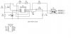
I didnt look at the circuit properly, lazy to check if the op-amp connection is right. It would be easier to read if the op-amp symbol is used instead of the DIP8 IC in your schematic.

If i were you, I would first manually tie the input of triac (thru resistor) to 3.0V voltage , see if this voltage and current are sufficient to turn it on.
If this poses no problem, then I would further investigate the op-amp circuitry.
 
I can't find a datasheet for TLC2712. Your connections are very suspect. There is no direct connection from the + side of the battery to the op amp. This is not normal. You need to post a real schematic and/or a link to a datasheet.
 
I agree, the diagram doesn't make sense
 
I Guess TI web site is down. But you can view the data sheet at https://www.electro-tech-online.com/custompdfs/2004/12/23917.pdf

I Know that the drawing dosn't look right but I been all over the circuit board and that Is how it is wired. I have one working board and one Bare board. So I know that the Layout can work, as I have 1 board working.

I realy Like to thank every one for looking and giving suggestions.
Guess I try to Hunt for a "Moc 3022" opto, dich the 3020. Are do any of you see anyway that I might get a little more output to the opto?

Steve
 
The connection of C1, R1 is VERY "unusual" :? This looks like it belongs in the feedback path.. R2 is even more confusing :? :?
 
A R6 is connected between Vdd ppin and 3V supply, this doesnt make sense. This will cause voltage drop, meaning your op-amp will get less than 3.0V. What make thing worse is, this voltage drop is proportional to the current drawn, this will make Vdd fluctuate if current drawn changes.
 
It looks like one of those circuits from "The Art of Electronics" where students must spot the mistakes :lol:
 
Look at figure 10 in the datasheet for the opamp. It can give only about 2mA (this is typical, it could be less) into the opto with a 3V supply. Even the expensive, rare and sensitive opto needs much more.
A poor choice of an opamp or a supply voltage.
 
audioguru said:
Look at figure 10 in the datasheet for the opamp. It can give only about 2mA (this is typical, it could be less) into the opto with a 3V supply. Even the expensive, rare and sensitive opto needs much more.
A poor choice of an opamp or a supply voltage.

And the 3K3 resistor shown in the power supply feed will limit the possible current to far less than that as well!.
 
Status
Not open for further replies.

New Articles From Microcontroller Tips

Back
Top