Continue to Site

Welcome to our site!

Electro Tech is an online community (with over 170,000 members) who enjoy talking about and building electronic circuits, projects and gadgets. To participate you need to register. Registration is free. Click here to register now.

  • Welcome to our site! Electro Tech is an online community (with over 170,000 members) who enjoy talking about and building electronic circuits, projects and gadgets. To participate you need to register. Registration is free. Click here to register now.

Need Help with Strobe controller speed

Status
Not open for further replies.
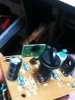
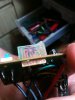
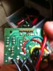
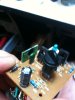
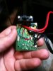
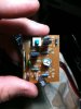
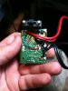
Ok so i bought this LED 12v strobe controller and it does what i want, flshed 1-1-1 to the left output and 1-1-1 to the right, but it does it slower than id like, so i opened it and it looks like something i could alter, i took pictures and hopefully somebody can interpret this circuit and tell me which capacitor(s) and or resistor(s) to change i also posted a video of how slow it is id like it to flash at the speed of a police strobe

**broken link removed**
 

Attachments

  • photo 2.jpg
    photo 2.jpg
    95 KB · Views: 196
  • photo 4.jpg
    photo 4.jpg
    99.7 KB · Views: 222
  • photo 3.jpg
    photo 3.jpg
    102.8 KB · Views: 190
Last edited:
I see there is a trimmer on that circuit (the blue part with a white cap that has a flat-head groove in it) try turning that and see if it speeds up.
 
What is the vertical board on the left hand side - it has several connections to it. The black blob could house an IC controller etc in which case the timing is likely to be in software.
 
i believe thats what it is but i would think with all these caps and resistors they would control the speed since theres also a pot to adjust speed, ill post a closer pic of the other little board
 

Attachments

  • photo 2-1.jpg
    photo 2-1.jpg
    106.5 KB · Views: 170
  • photo 3-1.jpg
    photo 3-1.jpg
    93.7 KB · Views: 185
  • photo 4-1.jpg
    photo 4-1.jpg
    117.4 KB · Views: 164
  • photo-10.jpg
    photo-10.jpg
    101 KB · Views: 165
Last edited:
There are two "blind" spots labelled 470Ω, and instead of R9 there is a wire jump.

Track the connections and find out if one of them is connected to the variable resistor.

Check all other resistors being connected to the pot. I'm sure there is a fixed value resistor in series with the pot to limit maximum speed.

Boncuk
 
Yep, both the 100k resistor and the wire link (R11) next to it are both in series with the trimpot. If you reduce the value of the 100k cap I'm sure that would speed up the flash rate.

Also the greencap (C2 ?) is attached directly to the trimpot and it very likely it is the timing cap it looks about the right size. You could try reducing the value of the cap.
 
ok so reduce the 100k resistor and the green cap's values? and if i do this what values should i sumstitute, i know theres some sort of formula for this i think lol ne1?
 
Try replacing the 100k with a 33k, that should give you 3 times faster flash rate when the pot is turned right up.

Or just replace the cap with one that is 1/2 the value or 1/3 the value, which will give a better adjustment of speed with the pot.
 
Status
Not open for further replies.

Latest threads

New Articles From Microcontroller Tips

Back
Top