Continue to Site

Welcome to our site!

Electro Tech is an online community (with over 170,000 members) who enjoy talking about and building electronic circuits, projects and gadgets. To participate you need to register. Registration is free. Click here to register now.

  • Welcome to our site! Electro Tech is an online community (with over 170,000 members) who enjoy talking about and building electronic circuits, projects and gadgets. To participate you need to register. Registration is free. Click here to register now.

Need Help With Sound Acivated LED Project

Status
Not open for further replies.
OK, that says a lot. The little circuit that Audio Guru posted is a good example of a nice simple little circuit that will work and work well. I see you mention:


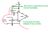
First LEDs have a forward voltage Vf which is the voltage they work at. They also have a forward current If which is the amount of current they draw. We know the Vf for your LEDs is between 3.0 and 3.6 volts but your LEDs really arent well suited for this type of application. When I looked up your LEDs unfortunately they don't list the forward current. Really matters not as was mentioned the LEDs you are using are not at all suited for an application like this. More on that later.

You mention you are using the audio out from your PC to drive a Corsair Amplifier. So what is really happening is a low level audio signal also called Line Out. Line Out is about a maximum signal level of 2 volts peak to peak or 1 volt peak or actually .7 volts RMS from a source impedance around 100 to 600 Ohms. So if we use Line Out to drive something those rough parameters need to be considered. Obviously your amplifier out uses a larger signal to drive the speakers.

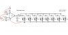
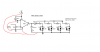
Note how Audio Guru's circuit starts from the music source so we can vary the signal driving the LM386 amplifier. The amplified output of the LM386 then drives the back to back LEDs in pairs. There are some resistors labeled R lacking a value. This is intentional as the value of R will be selected to limit the current to the LEDs based on... Ta Da the If (Forward Current) of the LEDs. That is why with a good circuit we need to know the If of the LEDs used.

Ron
Okay I'm going to try to understand this schematic from Audioguru.

From the music source...
-The ground wire connects to the positive end and 4th pin of the LM386 (Where does the ground wire connect to?)
-Another wire(?) connects from the music source to a 100k resistor and then to the ground (Not sure what the arrow from pin 3 on the LM386 to the resistor means)

Above the music source is the power supply...
-The 9V battery or wall battery connects to a positive end of a 470uF capacitor AND pin 6 on the negative side of LM386
-While the negative side of the same 470uF capacitor connects to a ground wire and pin 2 on the negative side of the LM386 (Where does this ground connect to, and where am I getting a ground wire from?)

Moving onto the LM386...
-Pin 5 connects to another positive end of 470uF capacitor
-Pin 5 also connects to a 0.05uF capacitor (Not sure where positive or negatives are on this one)
-On the other end of the 0.05uF it is connected by a 10(10 what?) resistor
-That resistor is connected to a ground wire from the first set of LED lights

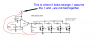
So these 4 LED lights are wired parallel...
-I have no clue what the 'until the current is too high for the LM386' means
-Or the dotted lines near the bottom right of the second set of LED lights

Am I understanding this at all?

How would this differ if I wanted 6-8 LED lights, would I just wire in some more lights in sets of twos parallel and depending on those, up the power supply voltage and the resistors connected to the sets of twos?

Would this effect the capacitors?
 
I might think about doing this project with a TIP31C and 5 red LED's with a 60Ω equivalent resistor in series with 12V supply... Hopefully it will work :)
The horrible circuit will work with a 60 ohm resistor exactly as it does now without the resistor. It won't work properly because it is missing many important parts.

The circuit I posted is very simple with only a few parts and it works perfectly. It can light up to 36 LEDs when it is powered from 9VDC.

The audio output from a computer (that feeds an external amplifier) is line level. The horrible circuit has a transistor that is not even biased so it needs an input of at least 0.7V for it to turn on.
But Line level is too low to turn on a transistor. Peaks of sound might make it turn on a little and dimly light the LEDs as you have.

The color organ circuit has the first transistor properly biased so a very small signal makes it work and turn on the next transistors which brightly light the LEDs.
 
The horrible circuit has a transistor that is not even biased so it needs an input of at least 0.7V for it to turn on. .

Is there a way to move the signal up 0.7v? As in have 0.7 as the carrier (central voltage)

And I used my phone audio output which had A reading of max of 4.5V (AC) on my DMM and the calculated RMS value is around 3.2V which is more than the turn on voltage for the TIP32C.

I just used old boiler parts to construct this as it was instantly available and i noticedko;7 that you have used an op amp, is it possible that the same colour organ circuit can be made using other op amps? for example the LM741?
 
The ground wire connects to the positive end and 4th pin of the LM386 (Where does the ground wire connect to?)
-Another wire(?) connects from the music source to a 100k resistor and then to the ground (Not sure what the arrow from pin 3 on the LM386 to the resistor means)
All grounds in the schematic are connected together. The input cable ground wire, pin 2 and pin 4 of the LM386 amplifier IC, the negative wire of the 470uF capacitor, the 10 ohm resistor and one wire of all the LEDs. Pin 2 of the IC is its negative signal input which is ground.

Positive signal input pin 3 of the IC connects to the slider (the arrow) on the 100k volume control that adjusts the amount of brightness.

-The 9V battery or wall battery connects to a positive end of a 470uF capacitor AND pin 6 on the negative side of LM386
-While the negative side of the same 470uF capacitor connects to a ground wire and pin 2 on the negative side of the LM386 (Where does this ground connect to, and where am I getting a ground wire from?)
The positive terminal of the battery or power supply connects to pin 6 of the IC and to the positive wire of the 470uF capacitor. The negative terminal of the battery or power supply connects to ground. Connect all the grounds together.

-Pin 5 connects to another positive end of 470uF capacitor
Yes.

-Pin 5 also connects to a 0.05uF capacitor (Not sure where positive or negatives are on this one)
They do not make 0.05uF capacitors anymore. Use 0.047uf (which is also called 47nF) instead. Such a low value does not have positive and negative wires.

-On the other end of the 0.05uF it is connected by a 10(10 what?) resistor
10 ohms.

-That resistor is connected to a ground wire from the first set of LED lights
Connect all the grounds together. The schematic uses ground symbols so that it does not have ground wires all over it.

So these 4 LED lights are wired parallel.
No. TWO LEDs are in parallel but with opposite polarities and each set of two LEDs has its own current-limiting resistor.

-I have no clue what the 'until the current is too high for the LM386' means
The datasheet for the LM386 amplifier shows that when it has a 9V supply its maximum output level is 6V peak-to-peak (3V peak) into an 8 ohm speaker. Then Ohm's Law calculates its maximum current is 3V/8 ohms= 375mA. An ordinary LED is rated for 20mA so simple arithmetic shows that the amplifier IC can driver up to 375mA/20mA= 18 LEDs in each direction.

-Or the dotted lines near the bottom right of the second set of LED lights
The dotted lines are the signal and ground wires for additional LEDs not shown on my schematic.

How would this differ if I wanted 6-8 LED lights, would I just wire in some more lights in sets of twos parallel and depending on those, up the power supply voltage and the resistors connected to the sets of twos?
The LEDs DO NOT connect to the power supply voltage. My schematic shows only two sets of two LEDs, each with its own current-limiting resistor. Add more pairs of LEDs each with its own current-limiting resistor as shown by the dotted lines.

Would this effect the capacitors?
The 470uf value of the capacitor feeding the resistors that feed the LEDs was calculated to drive up to 36 LEDs. If you use only 8 LEDs then the capacitor value could be reduced to (8/36) x 470uF= about 100uF.
 
All grounds in the schematic are connected together. The input cable ground wire, pin 2 and pin 4 of the LM386 amplifier IC, the negative wire of the 470uF capacitor, the 10 ohm resistor and one wire of all the LEDs. Pin 2 of the IC is its negative signal input which is ground.

Positive signal input pin 3 of the IC connects to the slider (the arrow) on the 100k volume control that adjusts the amount of brightness.


The positive terminal of the battery or power supply connects to pin 6 of the IC and to the positive wire of the 470uF capacitor. The negative terminal of the battery or power supply connects to ground. Connect all the grounds together.


Yes.


They do not make 0.05uF capacitors anymore. Use 0.047uf (which is also called 47nF) instead. Such a low value does not have positive and negative wires.


10 ohms.


Connect all the grounds together. The schematic uses ground symbols so that it does not have ground wires all over it.


No. TWO LEDs are in parallel but with opposite polarities and each set of two LEDs has its own current-limiting resistor.


The datasheet for the LM386 amplifier shows that when it has a 9V supply its maximum output level is 6V peak-to-peak (3V peak) into an 8 ohm speaker. Then Ohm's Law calculates its maximum current is 3V/8 ohms= 375mA. An ordinary LED is rated for 20mA so simple arithmetic shows that the amplifier IC can driver up to 375mA/20mA= 18 LEDs in each direction.


The dotted lines are the signal and ground wires for additional LEDs not shown on my schematic.


The LEDs DO NOT connect to the power supply voltage. My schematic shows only two sets of two LEDs, each with its own current-limiting resistor. Add more pairs of LEDs each with its own current-limiting resistor as shown by the dotted lines.


The 470uf value of the capacitor feeding the resistors that feed the LEDs was calculated to drive up to 36 LEDs. If you use only 8 LEDs then the capacitor value could be reduced to (8/36) x 470uF= about 100uF.
Okay I think I understand this now. I kind of drew over your schematic so it would be easier for me to read and understand. How does this look?
 

Attachments

  • led schematic.png
    led schematic.png
    20.2 KB · Views: 155
You have a wire that connects the positive terminal of the battery to the negative terminal of the battery which is a dead short.
When you short a battery it kills it and makes it very hot.

Also you show 16 LEDs instead of only 8 LEDs.
 

Attachments

  • Your wiring.png
    Your wiring.png
    11.6 KB · Views: 145
You have a wire that connects the positive terminal of the battery to the negative terminal of the battery which is a dead short.
When you short a battery it kills it and makes it very hot.

Also you show 16 LEDs instead of only 8 LEDs.
How does this look now?
 

Attachments

  • led schematic.png
    led schematic.png
    25.2 KB · Views: 165
I see what happened. Where power is +9 it looks like you have the red tied to the +9 and that is the same red that ties all the grounds together. I assume they really aren't connected that way as a short. I see the added - and + indicating they are two lines and not tied but think that is the point of some confusion.

Ron
 

Attachments

  • LED CKT Tie.png
    LED CKT Tie.png
    29.7 KB · Views: 254
I see what happened. Where power is +9 it looks like you have the red tied to the +9 and that is the same red that ties all the grounds together. I assume they really aren't connected that way as a short. I see the added - and + indicating they are two lines and not tied but think that is the point of some confusion.

RonView attachment 86503
Yeah they aren't tied. The one negative part of and and positive part of it. Sorry for confusion.
 
How does this look now?


Edit: You beat me Ron LOL

Edit: I see it now. - + on both is unnecessary; just showing you have grounds on one rail will let everyone know it's tide to a common ground. Just the positive 9+ is good enough.
 
Last edited:
Your still grounding to the negative rail on pin 4 of the Op-Amp.

Edit: You beat me Ron LOL

Edit: Edit: I see it now. - + on both is unnecessary; just show grounds on one rail and everyone will know it's tide to common ground.
Okay now I'm extra confused. Do you mind just editing it to the correct way?
 
There you go; does that make more sense. Sorry about confusing you.

Good luck on your project hope it all works out for you.
 
We assume this symbol is power ground;
earth_ground.gif

And that they are all tied together with the negative of the supply.
We do not connect all of them to keep schematics uncluttered.
 
Sorry....does what make more sense?

I just removed some of what I said in post #31 to try and clear up any confusion you have. It's a verbal edit: not to edit your drawing. Your fine with the way your going to do the project. However, in the future note that a "rail" is one wire connecting to multiple points. In this case it is the Positive Rail and the Negative Rail The "dots" are ties to the rails.
 
We assume this symbol is power ground;
earth_ground.gif

And that they are all tied together with the negative of the supply.
We do not connect all of them to keep schematics uncluttered.
I understand that but I'm doing it so that I could understand the schematic better. I'm new to this stuff just trying to tackle this project.
 
Status
Not open for further replies.

Latest threads

New Articles From Microcontroller Tips

Back
Top