icarii
New Member
I just found this site and I am hoping someone could help with a small project I am working on.
I am designing a circuit to control a pop-up ghost for our halloween hay ride party we do every year. Basically, a tractor will run over a pressure switch which will activate a screaming ghost that pops up with and air cylinder for 6 seconds. I have built the circuit using a LM386, but that was not load enough. So I am now using a TDA2003 with a 8ohm 10w speaker. I have tested the circuit on a bread board and it seams to work great.
I have taken electronics at a Votec about 15 years ago. So I understand how circuits work and such. But I am not sure about how to figure the math on this circuit. And I was hoping someone with a lot for experience and knowledge would look at the circuit and give me some pointers or ways to make it better.
Not sure if I need to explain what I am doing with the circuit, so here goes.
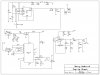
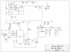
When the trigger switch is activated it sends a low signal to the 555 timer circuit which sends a high signal to the relay and a LM7808 (to kick it down to 5v). The out put of the LM7808 goes to 2 LED (for eyes) and an OR circuit to reverse the signal to low which goes to an ISD1110 (audio recording chip upto 11seconds). the recording chip then sends the audio to the TDA2003.
Any help anyone could give me would be great. Thanks
I am designing a circuit to control a pop-up ghost for our halloween hay ride party we do every year. Basically, a tractor will run over a pressure switch which will activate a screaming ghost that pops up with and air cylinder for 6 seconds. I have built the circuit using a LM386, but that was not load enough. So I am now using a TDA2003 with a 8ohm 10w speaker. I have tested the circuit on a bread board and it seams to work great.
I have taken electronics at a Votec about 15 years ago. So I understand how circuits work and such. But I am not sure about how to figure the math on this circuit. And I was hoping someone with a lot for experience and knowledge would look at the circuit and give me some pointers or ways to make it better.
Not sure if I need to explain what I am doing with the circuit, so here goes.
When the trigger switch is activated it sends a low signal to the 555 timer circuit which sends a high signal to the relay and a LM7808 (to kick it down to 5v). The out put of the LM7808 goes to 2 LED (for eyes) and an OR circuit to reverse the signal to low which goes to an ISD1110 (audio recording chip upto 11seconds). the recording chip then sends the audio to the TDA2003.
Any help anyone could give me would be great. Thanks