Continue to Site

Welcome to our site!

Electro Tech is an online community (with over 170,000 members) who enjoy talking about and building electronic circuits, projects and gadgets. To participate you need to register. Registration is free. Click here to register now.

  • Welcome to our site! Electro Tech is an online community (with over 170,000 members) who enjoy talking about and building electronic circuits, projects and gadgets. To participate you need to register. Registration is free. Click here to register now.

need help with NAND gate

Status
Not open for further replies.

salutka

New Member
Hi,
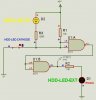
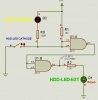
Im trying to get the LED on my PC to be ON all the time and cut when there is HDD activity. Well I found out that the motherboard controls the cathode to blink the led. I have included a schematic of what I built, for some reason I can't get it to work right. If anyone has any ideas why please let me know!

Thanks in advance.
 

Attachments

  • 7400.PNG
    7400.PNG
    25.8 KB · Views: 650
Either that ancient 7400 is pulling too many AMPS for your poor power supply or your computer uses TTL logic or has Schmitt trigger characteristics.

The logic threshold for TTL is 1.4 volts; a voltage below 1.4 volts is considered to be logic 0 while voltage above 1.4 is considered to be logic 1.

CMOS is 50% of Vdd.

Schmitt trigger logic 0 is approximately 15% of Vdd and the threshold for logic 1 is about 85% of Vdd.
 
I don't know how you have the 7400 powered. If you are using an external source be sure to tie the grounds together.

Otherwise, measure the voltage you get out of the transistor and see if its enough to trigger the gate.
 
TTL devices are not good to source current.

You are trying to source 50 mA of current.

And your PNP transistor isn't working, if you check, there will be 5V on its collector. You'll have to add a pulldown resistor there.
 
Last edited:
Hi,

all you want is just invert the LED to light up when there is no HDD activity.

You might choose either way shown in the attachment.

Inverting the signal using a NAND-chip leaves three gates unconnected and requires some space. Additionally CMOS-gates won't source 20mA at 5V. Therefor I used a low current LED (2mA)

With a simple PNP-transistor the result is the same, requiring less space and you might use any standard LED (20mA).

Boncuk
 

Attachments

  • HDD0.gif
    HDD0.gif
    9.3 KB · Views: 319
  • HDD1.gif
    HDD1.gif
    9.3 KB · Views: 248
  • HDD2.gif
    HDD2.gif
    9.3 KB · Views: 282
correction

Boncuk
 

Attachments

  • HDD-ACT.jpg
    HDD-ACT.jpg
    21 KB · Views: 241
  • HDD-INACT.jpg
    HDD-INACT.jpg
    21.4 KB · Views: 296
Boncuk:
I checked the spec sheets of a 4011 NAND gate:

**broken link removed**

and can't see where it says it won't source the 20mA at 5 volts (100mW). Is it listed there, and I just don't know what I am looking for?
 
Boncuk:
I checked the spec sheets of a 4011 NAND gate:

**broken link removed**

and can't see where it says it won't source the 20mA at 5 volts (100mW). Is it listed there, and I just don't know what I am looking for?

Hi jmb4370,

you should look up the DC specifications.

Drive current (IOH) at VDD=15V is 13.5V at -2.4mA,
Sink current (IOL) at VDD=15V is 1.5V at 2.4mA.

Use the STM (ST Micro) (HFC4011) data sheet. It is very clearly to read.

Regard

Boncuk
 
Thanks for the explanation and the STM data sheet is indeed much clearer; is that often the case?

Does a Drive Current with a neg value (-2.4 mA) just indicate that it can SOURCE only 2.4 mA?

A standard LED could be used if the output of the NAND gate were connected to the base of a transistor, correct?
 
On their datasheets, Texas Instruments show curves of typical and minimum output current of their CD40xx Cmos gates and inverters at 5V, 10V and 15V supply voltages and with various output voltages down to a shorted output.

With a 5V supply the typical current into a 2V red LED (without a current-limiting resistor) is only 3.5mA. With a 10V supply the typical current into a 2V red LED (without a current-limiting resistor) is 14mA to 18mA.
 
The inputs on 7400 series ICs pull up quite strongly. You have to pull them down very near to ground to make the input low. It is usual to have a pull up resistor and a switch or transistor to ground.

The outputs are also asymmetrical. They can sink a lot more current than they can source, so you should connect the LED between +5 V and the gate output, via a resistor.

https://www.electro-tech-online.com/custompdfs/2009/05/sn74ls00.pdf gives the specifications. A low input should be less than 0.8 V and 1.6 mA will flow to ground from the output.
A high output can only provide 0.4 mA and may only rise to 2.4 V, so not enough to light an LED. A low output can take in 16 mA and it will fall to 0.4 V (leaving 4.6 V to the power supply) so it can light an LED.
 
Status
Not open for further replies.

Latest threads

New Articles From Microcontroller Tips

Back
Top