Continue to Site

Welcome to our site!

Electro Tech is an online community (with over 170,000 members) who enjoy talking about and building electronic circuits, projects and gadgets. To participate you need to register. Registration is free. Click here to register now.

  • Welcome to our site! Electro Tech is an online community (with over 170,000 members) who enjoy talking about and building electronic circuits, projects and gadgets. To participate you need to register. Registration is free. Click here to register now.

Need help with motorcycle charging system

Status
Not open for further replies.

barnett468

New Member
Hello;

My apologies if this is in the wrong section.


I have a problem with my 1974 Kawasaki 90 6 volt charging system and was hoping someone here could help. I know very little about electronics so please bear with me. The battery quickly looses power after using the signals and rear brake because the charging system does not put out enough voltage to charge the battery.

The stator is not an oil bath type. It is basically a dirt bike type with a separate coil for the turn signals and brake light. The other coil runs the engine, headlight, and running light.

It uses a very small rectifier only to convert the ac to dc. There is no regulator. The rectifier has 2 leads and a metal ground strap.

The battery charging coil puts out around a maximum of 10.5 volts ac rms (not peak voltage)? at around 2500 rpms and above. I'm guessing it is rms voltage because I am using a cheap voltmeter and was told they only read rms.

The rectifier puts out around 5.2 volts dc to the battery at around 2500 rpms and above. This is with the original rectifier and a new factory one. This is not enough voltage to charge the 6 volt battery.

All the wire connections are clean.

The battery charging coil has 1.5 ohms which is within the mfg's spec.

The flywheel has good magnetism.

The battery is a new wet cell type from the original mfg YUASA (although it is now made in taiwan instead of japan) and it reads around 6.2 volts when fully charged with the engine and lights turned off.

I was told that dc voltage is the same as ac rms voltage. In other words, if a system puts out 10 volts ac rms, it will put out 10 volts dc (possibly minus some small loss from going thru the rectifier), after it is rectified.


1. The battery charging system had to have put out slightly more voltage when the bike was new, otherwise, every one of them would have had to been repaired under warranty, therefore, based upon this assumption, why do you think it now puts out slightly less voltage than it did when it was new.

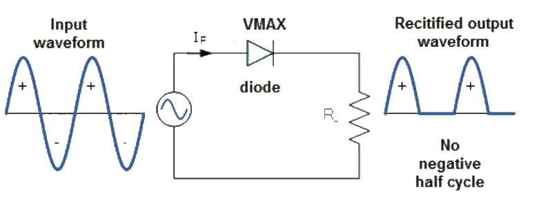
2. I read that a half wave rectifier will only put out half of the ac rms voltage, meaning that if it has 10 volts ac rms going in, it will only put out 5 volts dc. I also read that a full wave rectifier will put out the same amount of dc as the ac rms going into the other side. Is this correct?

3. If the answer to question number 2 is yes, is it possible that the factory rectifier is a half wave type instead of a full wave type?

4. Is there a way to tell if a rectifier is a half wave or full wave type?

5. If my rectifier is a half wave type, and a full wave type will put out more dc voltage than the original one currently is, where can I find one that will work? I have seen them on Amazon for as little as $6.00.

6. If a full wave rectifier will put out more voltage than I need, is there a cheap and easy way to regulate/limit the amount of peak dc voltage it puts out without having to reinvent the wiring harness?

7. Is there a ready to use 6 volt full wave rectifier/regulator combo that will work for this app?


Thanks for any help

.
Here's the rectifier


.

.

.
 
Last edited:
Welcome to ETO!
The rectifier shown is a half-wave type.
Your meter won't give an accurate reading when measuring half-wave rectified voltages, so ignore the 5.2V reading. The 10.5V reading is also suspect since the coil output is unlikely to be a constant sine-wave.
A 10.5V rms AC sine-wave has a peak voltage of about 14.8V. When half-wave rectifed the rectifier output, if unloaded, would have peaks of around 14V but an average of only about 4.5V.
Because the coil has one end grounded, and so do the lamps, you can't use a full-wave rectifier.

Thanks very much for your reply.

1. I know it is not putting out enough voltage to charge the battery because it gets low if I use the turn signals and brakes a lot, so even if my voltmeter is not accurate, the dc voltage out to the battery is still less than what is needed to keep the battery charged, so based upon this, is there anyway to get more dc volts to the battery?

2. Is there something to more accurately measure the dc voltage with? I have used a voltmeter for doing this for 45 years.

3. Does a regular budget type voltmeter read the dc voltage to a battery more accurately if the charging system uses a rectifier/regulator like automobiles do?

Thanks again.
 
a volt meter reads DC great, but a oscilloscope is required to read waves

Unfortunately this does not answer any of my questions.

Volt meters have a setting to read ac.

Anytime any auto mechanic checks alternator output (dc) at the battery, they use a volt meter. All the service manuals say to use a volt meter. None of them say to use a scope, therefore, a voltmeter is good enough for the manufacturers.

Also, alec_t says my voltmeter may not read dc accurately but you say it's good enough.

I actually don't need to read ac, I only need to read dc.

The bottom line is I need to have more voltage going to the battery, so how can I do this?

Are there half wave rectifiers that may be more efficient than my stock one that will put out more dc to the battery?

.
 
Last edited:
yes but ac voltmeter is 60hz only
and mechanic may measure DC at the battery which is after rectifier and smoothing capacitor, but that is only volts

bottom:
My suggestion is to try a new coil, a voltmeter alone wont tell you amps under a load which is what a mech does to test a battery , not just volts. also if only a few windings are blown it may not reflect in dc volt testing,
since there is no current draw a rectifier could easily charge up to and hold at the required voltage with just one coil left since the only draw is the internal load of the voltmeter which is high resistance

Thanks for your reply, however, my current coil tests on the high side of the factory range, which I would think suggests that it is working perfectly, because if the wires were shorted inside the coil, it would have lower resistance than the factory spec, plus there are no new coils available. This is a 1974 model and most of the parts have been discontinued.

This seems to me that the only other option if there is no such thing as a more efficient rectifier than I already have, is to wind the coil so it has more resistance or something, however, I was told something like, if smaller wire is used to do this than what is currently on the coil, it would put out more voltage but less current or something like that, but these are things I don't understand, however, even if it does put out less current, is that going to be a problem in my case, and if it is going to be a problem can the coil be wound with the same size wire it currently has but with more turns to increase the resistance, thereby increasing the voltage.

Also, if the coil can be wound to increase the voltage, just how much resistance does the coil need to have to put out 2 - 3 more volts rms (because the half wave rectifier is going to cut that in half) . I don't think this question can easily be answered but I don't know, I would guess that it may depend on the amount of magnetism that is in the flywheel (which may be able to be measured with a gauss meter) and some fancy einstein like equation.

This being said, it seems like it would be more of a trial and error thing as to how many windings and how much resistance the coil would need.

What do you think?
.
 
Last edited:
Hi,
a lot of 1970s and earlier era magnets used materials that can weaken over time, especially if the magnet rotor has ever been removed and not fitted with a "keeper".

With some types they can lose a good part of their original strength within seconds unless they are transferred directly from the coil polepiece frame to a dummy iron replacement.


I'd replace the rotor/flywheel or get it re-magnetised. Any place that services such bikes should either be able to do it or know some place that can.

However strong the magnets appear to be now, I'll guarantee they are nothing like as strong as the were when new, if it's still got the original set - and electrical output is directly proportional to magnetic field strength.

A quick search: https://www.scooterwest.com/flywheel-re-magnetizing-labor-remag.html
 
Been there done that, such electrical systems are total crap - I never managed to find a decent solution. Basically there's not enough energy developed by the crude 'alternator'.

I had a Yamaha DT400, and I was considering trying to convert it to 12V (so less loss through switches and wires), a decent size battery, and a proper charging circuit - using both the charging coil and the lighting coil. However, as it was my only means of transport, I never got round to it.

As already mentioned, the rectifiers are only half wave with the coils grounded, so you're wasting 50% of the generated energy anyway.

My 'plan' was to separate the coils from chassis, then separate the ground connections of the two coils, and fit bridge rectifiers on both then combine the outputs - from there through a charging system to a decent size battery - and having that feeding the headlights as well as the rest of the electrics.

Following on from that, I planned to rewind the coils to make the system 12V - but as I said, it never happened, as I was using the bike every day.

For those you have never ridden such bikes, you pull up at a junction, your headlight fades to almost nothing, and after a few seconds the indicators start to fail as well - particularly if you have the brake light on. It's an absolute pain! :D
 
3. Does a regular budget type voltmeter read the dc voltage to a battery more accurately if the charging system uses a rectifier/regulator like automobiles do?
With a regulator the charging voltage would have less ripple, so be steadier for a meter to read, but (a) if the regulator were a series type there would be less charging voltage available and (b) if it were a shunt type (more likely) then some charging current would be wasted to ground.
 
Last edited:
Bit of a longshot, but if a suitably rated off-the-shelf cheapo AC-DC boost converter, or a DC-DC boost converter that could be persuaded to run from a half-wave rectified supply, could be found, that might be a way of raising the charging voltage.
 
Been there done that, such electrical systems are total crap - I never managed to find a decent solution. Basically there's not enough energy developed by the crude 'alternator'.

I had a Yamaha DT400, and I was considering trying to convert it to 12V (so less loss through switches and wires), a decent size battery, and a proper charging circuit - using both the charging coil and the lighting coil. However, as it was my only means of transport, I never got round to it.

As already mentioned, the rectifiers are only half wave with the coils grounded, so you're wasting 50% of the generated energy anyway.

My 'plan' was to separate the coils from chassis, then separate the ground connections of the two coils, and fit bridge rectifiers on both then combine the outputs - from there through a charging system to a decent size battery - and having that feeding the headlights as well as the rest of the electrics.

Following on from that, I planned to rewind the coils to make the system 12V - but as I said, it never happened, as I was using the bike every day.

For those you have never ridden such bikes, you pull up at a junction, your headlight fades to almost nothing, and after a few seconds the indicators start to fail as well - particularly if you have the brake light on. It's an absolute pain! :D

Thank you for your reply.

Are you saying that you had your flywheel remagnetized and it did not increase the output?

Is it possible for my flywheel to end up having less magnetism after it is remagnetized if the magnetizer is not as strong as the one the factory used. In other words, can a low level magnetizer actually suck out (remove) some of the magnetism?

Yeah, these systems are budget for sure and were designed to save weight and cost over a typical oil bath 12 volt system or whatever.
 
Hi,
a lot of 1970s and earlier era magnets used materials that can weaken over time, especially if the magnet rotor has ever been removed and not fitted with a "keeper".

With some types they can lose a good part of their original strength within seconds unless they are transferred directly from the coil polepiece frame to a dummy iron replacement.


I'd replace the rotor/flywheel or get it re-magnetised. Any place that services such bikes should either be able to do it or know some place that can.

However strong the magnets appear to be now, I'll guarantee they are nothing like as strong as the were when new, if it's still got the original set - and electrical output is directly proportional to magnetic field strength.

A quick search: https://www.scooterwest.com/flywheel-re-magnetizing-labor-remag.html

Thanks for your reply.

After researching my problem over the past few months and using simple deductive reasoning (which may be absolutely wrong, lol), it was my best guess that the flywheel had lost some magnetism for whatever reason, so I actually contacted the biggest motorcycle electric company in the US and scooter West, and asked them what they thought, and after I told them how well a screwdriver sticks to the magnets on the flywheel, they said that it had more than enough magnetism to generate as much voltage as the system as a whole was capable of. They also told me that unless the flywheel was removed and left sitting for a long time, or unless it was hit hard from a crash etc, that it would be nearly impossible for it to have lost enough magnetism for the stator to produce less voltage.

Scooter West also told me that they bought the remagnetizing machine to remagnetize the flywheels on old vespas, because they were so weak to start with the signals wouldn't work at idle when the bikes were new, amd their flywheels did loose magnetism, so even though they advertise that they can remagnetise flywheels, and that they can do different brands etc, their machine gives the best results on the type of flywheels the vespas have, however, again, since they don't have a gauss meter, they really don't know for certain how much improvement, if any, their machine can make on a flywheel like mine that seems to have good magnetism when using the screwdriver test. They said that the screwdriver test works ok when testing their vespa flywheels because they have such low magnetism to start with that nearly any increase is noticeable, but it is very hard to tell any improvement using the screwdriver test on a flywheel that has strong magnetism to start with.

Obviously both companies could be wrong, and scooter west said that they could remagnetize my flywheel, however, they did not have a gauss tester to test how strong the magnets are now and how strong they would be after they remagnetized it, and they did not know if it was possible for my flywheel to end up with less magnetism than it started with, and because of this, I am hesitant to have it remagnetized unless I can determine for certain whether or not it can end up with less magnetism, because if it can, then I am screwed, because as I mentioned, there are no parts available for this and I would have just turned a good running motorcycle into a non usable one.

.
 
Last edited:
With a regulator the charging voltage would have less ripple, so be steadier for a meter to read, but (a) if the regulator were a series type there would be less charging voltage available and (b) if it were a shunt type (more likely) then some charging current would be wasted to ground.

So is the answer to my question yes?

If so, and if my cheap voltmeter is not 100% accurate when reading ac rms voltage or dc voltage after a half wave rectifier that does not have a regulator, what would be a reasonable guess as to how inaccurate it is?

In other words, I am reading 10.5 ac rms before my half wave rectifier and 5.2 after it. If the voltmeter has an inaccuracy of 10%, at the best I would still only have 5.72 dc volts to the battery which is not enough. My point being, that even if the volt meter is not 100% accurate for reading my particular type of system, with a 10% inaccuracy it is still good enough for my purpose, but if it may be 30% inaccurate, I can only use it as a guide for comparing voltage output after I remagnetize the flywheel or rewind the charging coil etc, which will at least be better than nothing, and will still be helpful since even without the meter, I know that the system is not putting out enough volts to charge the battery, therefore I don't need a meter to confirm this, I only need it to tell me if any parts I change make it better or worse.

.
 
In other words, I am reading 10.5 ac rms before my half wave rectifier and 5.2 after it. If the voltmeter has an inaccuracy of 10%, at the best I would still only have 5.72 dc volts to the battery which is not enough

When you connect the meter after the rectifier but without a battery fitted, you see half-wave voltage; some voltage 50% of the time and no voltage 50% of the time.

half-wave-rectification.png


The meter tries to average that out, so shows roughly half the peak voltage that is really available for charging.

With a battery connected, it would be receiving current pulses all the time.


If you don't want to risk remagnetising it, how about fitting some LED lamps where practical, to reduce the overall lighting load current?
 
It is basically a dirt bike type with a separate coil for the turn signals and brake light. The other coil runs the engine, headlight, and running light.
I know it is not putting out enough voltage to charge the battery because it gets low if I use the turn signals and brakes a lot,

Those two quotes don't add up. How if the extra coil is for brakes and turn signals, have anything to do with the battery charging? You say all of the wire connections are good, does that include your grounds? Many people think that grounds in a vehicle don't mean anything when the actually do.
 
i dont think i would attempt coil repair personally, if coil change is out of question then a simple plan b i can think of would be to get lower power lights, without a load test its hard to say how much lower, plus that number will go down too as the coil deteriorates even more
 
Those two quotes don't add up. How if the extra coil is for brakes and turn signals, have anything to do with the battery charging? Y

There are usually two coils - one charges the battery, and this feeds indicators, brake light, side lights - everything except the headlight, which is fed directly from it's own coil. Having said that, there's actually three coils - the third one runs the ignition, totally independent of the rest of the electrics, and generates the high voltage sparks directly - no separate ignition coil.
 
Status
Not open for further replies.

Latest threads

New Articles From Microcontroller Tips

Back
Top