I have a Lathe with a turret (Hardinge) that switches tools by indexing (rotating CW only) from one position to another (8 positions). The computer that was on the machine died (1978 technology), and I am wanting to bring it up to date with new electronics. There are small relays on a 8x8 inch PC boards (not shown) that control larger ice cube relays on a larger PC board. I have finally traced out this two layer ice cube relay board to see where the wires went. Attached is a picture of the section (2 relays only) in question. If I connect the 24VRTN (ground) to a terminal on the second terminal strip, it connects to one side of the coil of the upper relay (K13-A) and starts the process. NOTE: The motor is a gear head synchronus motor which can change direction by switching two wires at bottom of K13 relay.
SEE DOWN BELOW FOR MY MAIN PROBLEM NOTE: MOTOR IS A SYNCHRONUS MOTOR THAT CAN CHANGE DIRECTION BY SWITCHING TWO WIRES.
FYI: Here is my estimate of what happens if you need it:
TURRET ACTUATION SEQUENCE (BEST ESTIMATE)
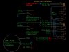
NOTE: Turret motor shaft pin is against back microswitch changing its state from C contacting NC to NO. This puts 24VRTN on from TB2-2 on K14-7, which is tied to K14-1 which goes nowhere. Forward microswitch is not active currently.
1. M10 (index turret command) puts a ground on TB2-18 which grounds K13-A activating relay K13.
2. K13-7 contacts K13-4 which is tied to K14-A but does nothing since the forward microswtch is open currently.
3. K13-9 PUTS 115VAC on K13-6 which is tied to K14-9 which contacts K14-3 putting 115VAC on TB1-14 which is tied to turret motor pin 2 which starts it turnning CW (as facing motor shaft).
4. When motor turns, the back microswitch switches to NC position taking ground off of K14-7.
5. Motor keeps turning enough to activate forward micro switch, then 24V RTN is applied to K14-A which activates relay K14.
6. K14-7 is now tied to TB2-8 LIM which did somthing with old electronics WHICH PROBABLY DID WHAT I NEED.
7. K14-8 is now tied to TB2-24V RTN which puts a ground on K14-5 (end of capacitor) to K13-7.
8. K14-9 is now tied to K14-6 & TB1-18 motor P3 which would turn it the other direction toward back microswitch.
If I put a 24V ground on the K13 coil, then the sequence above works just fine, except that when the motor is reversed and the pin on the shaft hits the back microswitch nothing happens, and I have to quickly remove the ground or I can break something.
On the small relay boards there are available SPST relays that I can use to help the situation, OR I could use some of the unused contacts in either of these two large relays.
SO, what i need help with is: I want the back microswitch to turn off the 24V GND and stop at the end of the indexing. While this sounds simple the problem, is if I run the 24VGnd through the switch initially, some how a voltage would need to get to the relay to start the sequence and keep it going to the very end. But, when the shaft starts to turn that microswitch will switch state and stop the sequence. So something needs to keep it going, but switch the microswitch before the shaft pin hits it, so it can break the 24V ground to stop the sequence. MY MAIN puzzle.
My thinking is that if there was some kind of relay flip flop using the small relays that would put 24VGnd on the K13 relay and start the sequence, then maybe the 24VGnd could be put on K14 pin 4 (says TB2-8 LIM NC) and then when that relay actuates during the second phase of the turret turning, it could flop the small relays and make the back microswitch ready to break the ground to K13 pin A. Now something has to FLIP the relays back into the intial state. VERY TRICKY!
Are all those capacitors used to kill transients or stop relay bounce??
This is a really complicated circuit, so I am sorry. If you can't follow it please let me know and I will try to add more explanation.
Any help would be greatly appreciated before my brain frys. All right, you clever people here is you test for the month!
Thanks - John
SEE DOWN BELOW FOR MY MAIN PROBLEM NOTE: MOTOR IS A SYNCHRONUS MOTOR THAT CAN CHANGE DIRECTION BY SWITCHING TWO WIRES.
FYI: Here is my estimate of what happens if you need it:
TURRET ACTUATION SEQUENCE (BEST ESTIMATE)
NOTE: Turret motor shaft pin is against back microswitch changing its state from C contacting NC to NO. This puts 24VRTN on from TB2-2 on K14-7, which is tied to K14-1 which goes nowhere. Forward microswitch is not active currently.
1. M10 (index turret command) puts a ground on TB2-18 which grounds K13-A activating relay K13.
2. K13-7 contacts K13-4 which is tied to K14-A but does nothing since the forward microswtch is open currently.
3. K13-9 PUTS 115VAC on K13-6 which is tied to K14-9 which contacts K14-3 putting 115VAC on TB1-14 which is tied to turret motor pin 2 which starts it turnning CW (as facing motor shaft).
4. When motor turns, the back microswitch switches to NC position taking ground off of K14-7.
5. Motor keeps turning enough to activate forward micro switch, then 24V RTN is applied to K14-A which activates relay K14.
6. K14-7 is now tied to TB2-8 LIM which did somthing with old electronics WHICH PROBABLY DID WHAT I NEED.
7. K14-8 is now tied to TB2-24V RTN which puts a ground on K14-5 (end of capacitor) to K13-7.
8. K14-9 is now tied to K14-6 & TB1-18 motor P3 which would turn it the other direction toward back microswitch.
If I put a 24V ground on the K13 coil, then the sequence above works just fine, except that when the motor is reversed and the pin on the shaft hits the back microswitch nothing happens, and I have to quickly remove the ground or I can break something.
On the small relay boards there are available SPST relays that I can use to help the situation, OR I could use some of the unused contacts in either of these two large relays.
SO, what i need help with is: I want the back microswitch to turn off the 24V GND and stop at the end of the indexing. While this sounds simple the problem, is if I run the 24VGnd through the switch initially, some how a voltage would need to get to the relay to start the sequence and keep it going to the very end. But, when the shaft starts to turn that microswitch will switch state and stop the sequence. So something needs to keep it going, but switch the microswitch before the shaft pin hits it, so it can break the 24V ground to stop the sequence. MY MAIN puzzle.
My thinking is that if there was some kind of relay flip flop using the small relays that would put 24VGnd on the K13 relay and start the sequence, then maybe the 24VGnd could be put on K14 pin 4 (says TB2-8 LIM NC) and then when that relay actuates during the second phase of the turret turning, it could flop the small relays and make the back microswitch ready to break the ground to K13 pin A. Now something has to FLIP the relays back into the intial state. VERY TRICKY!
Are all those capacitors used to kill transients or stop relay bounce??
This is a really complicated circuit, so I am sorry. If you can't follow it please let me know and I will try to add more explanation.
Any help would be greatly appreciated before my brain frys. All right, you clever people here is you test for the month!
Thanks - John