Continue to Site

Welcome to our site!

Electro Tech is an online community (with over 170,000 members) who enjoy talking about and building electronic circuits, projects and gadgets. To participate you need to register. Registration is free. Click here to register now.

  • Welcome to our site! Electro Tech is an online community (with over 170,000 members) who enjoy talking about and building electronic circuits, projects and gadgets. To participate you need to register. Registration is free. Click here to register now.

Need Help With LED Schematic

Status
Not open for further replies.

sjaguar13

New Member
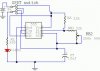
I got this schematic, but I don't understand it. Particularly the SPDT switch (It's supposed to be DPDT). All I want is a circuit that blinks LEDs faster or slower based on a 500K pot. The pot has a DPDT switch, so if I use the switch, the LEDs just stay on, but I can't figure out the schematic.
 

Attachments

  • 555led.jpg
    555led.jpg
    28.6 KB · Views: 795
Look carefully at the schematic and follow the connection from the positive side of the battery. With the switch in the position that is not shown there is a direct path from the positive terminal of the battery to the LED so all it can do is stay on. Print it out and use a colored pencil to trace what I'd call a normal path - then use another color and trace in the path for the other position of the switch - it's easier to see.

If the circuit is correct and the pot does control the speed then you might add a SPST switch, possibly some other resistors, to short out a resistor in that part of the circuit to get the two speeds that you want. As an alternative you might add a second pot and a SPDT switch so that you have control of the fast and slow - presuming that you can get the etremes you need with the pot(s) at zero or 100%.
 
Just toss the switch replace it with wires connected as the switch is drawn. Put your 500k pot in place of the 250k pot. You'll get an LED that blinks faster or slower depending on the setting of the pot.
 
I wired the thing, but all it does it stay on, no matter what. I'm going to try unhooking the switch and just wiring it straight through. The stupid pot and switch is hard to bread board, so I have to hold on to the 6 wires, and I think some of those are touching something they shouldn't be.
 
I got it to work, but I'm not liking it. The slowest it goes is way to fast. And the fastest it goes it basically not blinking at all. Is there a way to slow it down, like add another resistor? Also, I don't know if this is possible, but is there a way to make it go from really slow to really fast, changing the cap or something?
 
If you really have a 500k pot and a 10uF cap, the LED should blink once approximately every 7 seconds at the slow setting. If not, you have a bad part or you have the circuit wired incorrectly.
 
sjaguar13 said:
I think I found the problem then. I have a 0.1uF cap. What is the fastest it will blink with the 10uF cap?
There is a simple equation on p.8 of the LM555 datasheet that allows you to calculate the frequency of oscillation.
f=1.44/((RA+2*RB)*C)
In your case, if you have a 500k (500000 ohm) pot and a 10uF (.00001F) cap,
Fmax=1.44/(66k*.00001), or Fmax=2.18 Hz
Fmin=1.44/((22k+2*522k)*.00001) or Fmin=0.135 Hz, which is one flash every 7.4 seconds. Component tolerances, especially of the pot and the cap, can cause these numbers to be different by as much as 30%, or maybe more.
 
Status
Not open for further replies.

Latest threads

New Articles From Microcontroller Tips

Back
Top