Telemachus
New Member
Question first, and then longer explanation:
How do I eliminate the high voltage differential between a rectifier circuit and earth ground?
Now the wordy part:
I have embedded a cheap etekcity wireless outlet (https://www.etekcity.com/product/100068.html) into a bug fan to be able to control it with a reed switch connected to a door, so that when the door opens, the fan turns on. The idea was that the rf outlet gives me a way to turn it on via remote control, as well as automatically when the door is open. The outlet was much cheaper than creating my own wireless interface with a uC and relay.
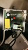
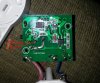
Attached is a picture of the PCB of the etekcity outlet. Blue wire on bottom right is neutral, left brown is Line in, and middle brown is line out.
Best I can tell, these outlets first drop the voltage to 24 volts through a coil on the opposite side, and then DC through a rectifier (U1). A voltage regulator (U2) drops the voltage down to 5V for the uC and RF unit. The uC on the top left controls the transistor (q1) through Pin 3 output with a current limiting resistor (R6). The relay is a 24V relay.
My idea was to use a hard wired Reed switch to either connect 5V VCC to the current limiting resistor that goes into Q1, or to connect the emitter to collector on Q1. Jumper wires on either of these seems to work well to control turn the relay on using a reed switch.
I embedded the circuit into the fan, wired it all up, and thought it would work great, since the exposed wires to the reed switch are 24V max.
However, one of the wires to the reed switch came into contact with the chasis of the fan, which is connected to earth ground, and popped the GFI. A little probing around confirmed that just about ANY spot on the PCB post rectifier (VCC, GND) in relation to earth ground, shows 110V (I'm not sure how much current, but enough to pop the GFI).
How do I eliminate the high voltage differential between a rectifier circuit and earth ground? I'd like to make sure that these wires to the reed switch are only capable of low voltage potential.
Thanks in advance!
How do I eliminate the high voltage differential between a rectifier circuit and earth ground?
Now the wordy part:
I have embedded a cheap etekcity wireless outlet (https://www.etekcity.com/product/100068.html) into a bug fan to be able to control it with a reed switch connected to a door, so that when the door opens, the fan turns on. The idea was that the rf outlet gives me a way to turn it on via remote control, as well as automatically when the door is open. The outlet was much cheaper than creating my own wireless interface with a uC and relay.
Attached is a picture of the PCB of the etekcity outlet. Blue wire on bottom right is neutral, left brown is Line in, and middle brown is line out.
Best I can tell, these outlets first drop the voltage to 24 volts through a coil on the opposite side, and then DC through a rectifier (U1). A voltage regulator (U2) drops the voltage down to 5V for the uC and RF unit. The uC on the top left controls the transistor (q1) through Pin 3 output with a current limiting resistor (R6). The relay is a 24V relay.
My idea was to use a hard wired Reed switch to either connect 5V VCC to the current limiting resistor that goes into Q1, or to connect the emitter to collector on Q1. Jumper wires on either of these seems to work well to control turn the relay on using a reed switch.
I embedded the circuit into the fan, wired it all up, and thought it would work great, since the exposed wires to the reed switch are 24V max.
However, one of the wires to the reed switch came into contact with the chasis of the fan, which is connected to earth ground, and popped the GFI. A little probing around confirmed that just about ANY spot on the PCB post rectifier (VCC, GND) in relation to earth ground, shows 110V (I'm not sure how much current, but enough to pop the GFI).
How do I eliminate the high voltage differential between a rectifier circuit and earth ground? I'd like to make sure that these wires to the reed switch are only capable of low voltage potential.
Thanks in advance!
Attachments
Last edited: