Continue to Site

Welcome to our site!

Electro Tech is an online community (with over 170,000 members) who enjoy talking about and building electronic circuits, projects and gadgets. To participate you need to register. Registration is free. Click here to register now.

  • Welcome to our site! Electro Tech is an online community (with over 170,000 members) who enjoy talking about and building electronic circuits, projects and gadgets. To participate you need to register. Registration is free. Click here to register now.

Need help with a project..

Status
Not open for further replies.

HatsVapes

New Member
okay I am building something that uses a specific variable voltage chip on it (allows you to adjust the output voltage from 0v to 7.2v i believe) the VV chip has a dial on it that is used with a screwdriver to adjust the voltage. the output voltage is displayed on an indicator and then runs out to what im using it on.

how do I make it so I can change the voltage with a push button rather than the dial? I just want 2 buttons, voltage up and voltage down. Im looking to make this as small as humanly possible because space is a huge issue. somebody please help?

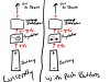
I added a basic drawing of how I need this to work..
 

Attachments

  • example.jpg
    example.jpg
    157.1 KB · Views: 146
There may be several possible ways to do it. What is the part number of the regulator?
 
DE-SWADJ is the regulator I will be using. it has a 25-turn pot on it but I need to figure out a digital pot basically one button moves the voltage up, one moves it down
 
What value (ohms) does the pot have?
 
It doesn't look like you can vary it's voltage with anything other than a pot seeing as how it's built into the board. You can cut the case open and remove it, but you may have some issues with getting it to interface proberly.
 
i know its possible ive seen people do it i just dont know how to do it and i figured somebody on here would know how..
 
This is what you have. Note the pot located on top of the unit. The unit would need to be hacked and the actual value of the pot used known. Once the pot value is known then it can likely be replaced with a digital pot. This would be an example of a digital pot. That pot uses a SPI interface and would need to be driven. That is a single example. There are other interfaces for digital pots. This may help with interfacing using an Arduino uC. So to answer your question, yes, it can be done. Can it be done really easy? Not quite. Can it be done with limits on space? No not really. Look at this selection from Analog Devices and pay attention to the interfaces. Note the Up/Down versions which would do what you want likely easily. So it is pretty much up to you how you go about it.

<EDIT>
Actually you would want one of these. Two buttons as you want.
</EDIT>

Ron
 
Last edited:
The one Ron posted would be nice, but it won't run at 7.2 volts. Seems like they should make the same thing for 12 volts and you would be home free. You also (according to this schematic) need one at 1K. Lets all have a good google. :D

https://forum.tsebi.com/viewtopic.php?f=4&t=29

Ron, How did you find this one?
 
okay I spoke with somebody in the chat and he suggested getting a diff regulator and a separate digital pot. He suggested a LM317 regulator with a MCP4262 digital pot and then using a PIC12 with some buttons wired in to control it.

edit: oh and ronv, we are both in tucson lol small world
 
Last edited:
Hi Hats,

Yes, I'm up in Saddlebrooke. How about you? (just saw your pm)
It won't be very small if you have to add all that "stuff". Do you have to have 7.2 volts or would 6.5 be enough? If so Ron's chip has everything you need. You could use a regular resistor to get the output to say 6.7 and use the chip to adjust it down from there.
 
im down almost by the base (i work on base) I would like to be able to hit 7.4 or even higher.. the LM317 goes all the way up to 37v if I so desired lol
 
The one Ron posted would be nice, but it won't run at 7.2 volts. Seems like they should make the same thing for 12 volts and you would be home free. You also (according to this schematic) need one at 1K. Lets all have a good google. :D

https://forum.tsebi.com/viewtopic.php?f=4&t=29

Ron, How did you find this one?

Google but I flunked on the posted voltages. Missed that. :)

Ron
 
Status
Not open for further replies.

Latest threads

New Articles From Microcontroller Tips

Back
Top